Rite-Ride 2212 User Manual
Page 3
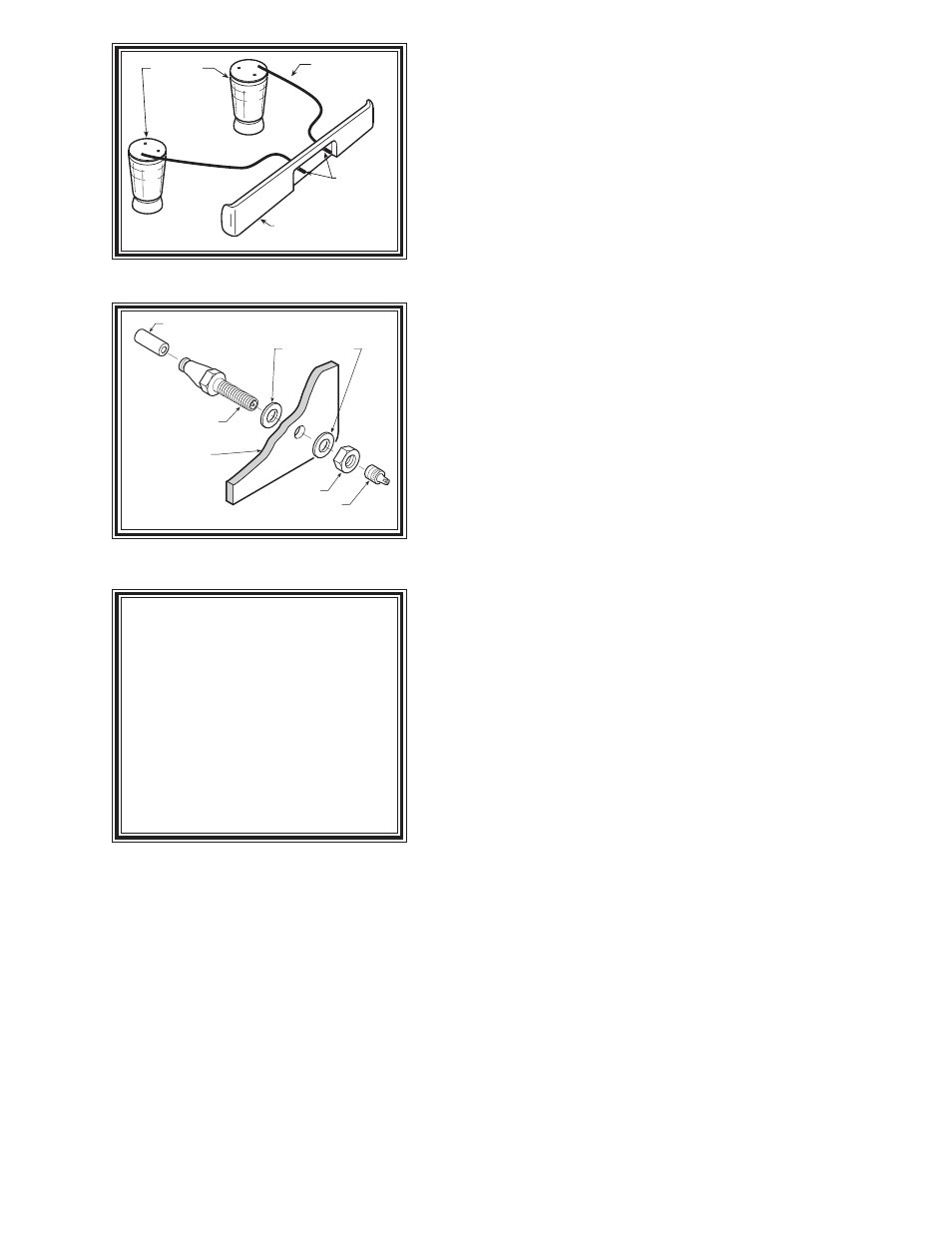
AIR LINE
PUSH-TO-CONNECT
INFLATION VALVE
FLAT WASHER
HEX NUT
VALVE CAP
BODY OF
VEHICLE
AIR HOSE
INFLATION
VALVES
BUMPER
AIR
SPRINGS
Figure "B"
Figure "C"
S
TEP
1 - P
REPARE
THE
VEHICLE
With the vehicle on a solid level surface chock the front wheels.
Raise the vehicle by the rear axle and remove the rear wheels. After
the removal of the wheels, lower the vehicle so the axle rests on jack
stands rated for your vehicles weight. Remove the negative battery
cable.
S
TEP
2 - P
REASSEMBLE
THE
KIT
Select one air helper spring from the kit. Install the upper
bracket by aligning the threaded holes on the air spring with the
small holes on the upper bracket. Fasten the upper bracket to the air
spring using the 3/8"-16 x 3/4" hex bolts as shown in Figure "A".
Install the air fitting as shown in Figure "A". Tighten the air fitting
so as to make contact with the nylon ring and then tighten 1/4 turn
to snug the fitting. No thread sealant is needed. Insert the two 3/8"-
16 x 3-1/2" carriage bolts into the lower bracket. Next, attach the lower
bracket and disk to the air spring using the 3/8"-16 x 3/4" hex bolt see
Figure "A". Refer to Figure "A" for proper orientation of the lower
bracket.
S
TEP
3 - A
TTACH
LOWER
BRACKET
TO
LEAF
SPRING
Place the assembly on the driver’s side on top of the leaf spring
stack forward of the axle see Figure "A". Attach the lower bracket
to the leaf stack using the 3/8"-16 x 3 1/2" carriage bolts (installed in
the lower bracket earlier), the flange lock nuts and bracket strap as
shown in Figure "A". Note that the lower bracket will sit on top of
the leaf spring with the bracket hook capturing the forward "U"-bolt.
The bracket strap is used to clamp the lower bracket to the leaf stack
see Figure "A".
S
TEP
4 - P
OSITION
THE
UPPER
BRACKET
ON
THE
FRAME
It is recommended that air pressure be added to the air spring at
this time to bring the upper bracket into position on the frame rail.
Cut a 6.00"-10.00" piece of air line tubing from the 18' roll . Install
one end into the elbow fitting located at the air spring, then place
one inflation valve on the other end of the air line (refer to step 9
for inflation valve installation). Once completed inflate the air
spring slowly (Do NOT inflate beyond 10 psi for this step). The
upper bracket will move upwards and fall into position on the
frame.
The portion of the upper bracket that is placed under the frame will rest against the bottom of the frame
rail on 4x2 vehicles. 4x4 vehicles must have at least 1/2" between the upper bracket and the under side
of the frame rail at the lowest point on the frame (Suggestion: use a 1/2" bracket strap included in the kit
between the upper bracket and the under side of the frame rail) see Figure "A". Note that the frame rail
is curved where the upper bracket is located, make sure there is a 1/2" of clearance between the upper
bracket and the lowest point on the frame see Figure "A".
S
TEP
5 - M
ARK
AND
DRILL
HOLES
IN
THE
FRAME
RAIL
Make sure the upper and lower brackets are parallel. With the air spring assembly in place, mark the
four holes to be drilled in the frame rail with a center punch. Drill the holes using a 3/8" drill bit. Before
drilling the holes make sure all electrical, brake and fuel lines are cleared from the path of the drill. In order
to prevent any damage to these lines it is recommended that a piece of wood be placed between the frame rail
and the existing lines while drilling.
NOTE:
Once the air helper springs
are installed, it is recommended that
the vehicle not be lifted by the frame,
as over-extension may occur, re-
sulting in damage to the air helper
springs. However, should it be-
come necessary to raise the vehicle
by the frame, deflate both air helper
springs completely.