Rite-Ride 2245 User Manual
Page 3
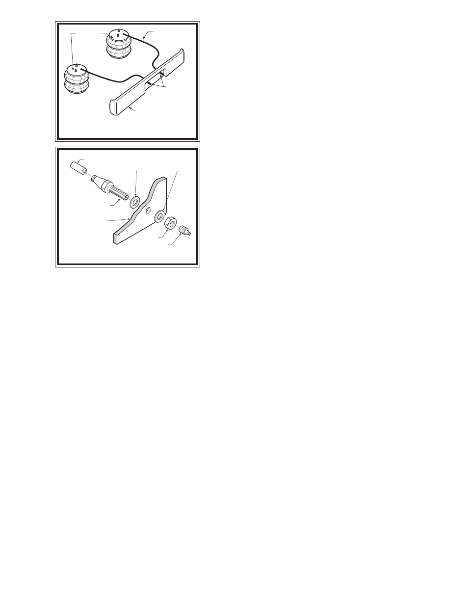
Figure "C"
AIR LINE
PUSH-TO-CONNECT
INFLATION VALVE
FLAT WASHER
HEX NUT
VALVE CAP
BODY OF
VEHICLE
Figure "B"
AIR HOSE
INFLATION
VALVES
BUMPER
AIR
SPRINGS
S
TEP
1 - P
REPARE
THE
VEHICLE
With the vehicle on a solid level surface chock the front wheels. Raise
the vehicle by the rear axle and remove the rear wheels. After the removal
of the wheels, lower the vehicle so the axle rests on jack stands rated for your
vehicles weight. Remove the negative battery cable.
S
TEP
2 - P
REASSEMBLE
THE
KIT
Select one air helper spring from the kit. Install the upper bracket by
aligning the studs on the upper bracket. Fasten the upper bracket to the air
spring using the 3/8"-16 hex nuts, as shown in Figure "A". Install the air
fitting as shown in Figure "A". Tighten the air fitting so as to make contact
with the orange sealant and then tighten. Insert the two 3/8"-16 x 3-1/2"
carriage bolts into the lower bracket. Next, attach the lower bracket to the air
spring using the 3/8"-16 x 3/4" hex bolt, see Figure "A". Refer to Figure "A"
for proper orientation of the lower bracket.
S
TEP
3 - A
TTACH
LOWER
BRACKET
TO
LEAF
SPRING
Place the assembly on the driver’s side on top of the leaf spring stack
forward of the axle see Figure "A". Attach the lower bracket to the leaf stack
using the 3/8"-16 x 3 1/2" carriage bolts (installed in the lower bracket
earlier), the flange lock nuts and bracket strap as shown in Figure "A".
Note that the lower bracket will sit on top of the leaf spring with the bracket
hook capturing the forward "U"-bolt. The bracket strap is used to clamp the
lower bracket to the leaf stack see Figure "A".
S
TEP
4 - P
OSITION
THE
UPPER
BRACKET
ON
THE
FRAME
The bracket must have at least 1/2" between the upper bracket and the
under side of the frame rail at the lowest point on the frame (Suggestion: use a 1/2" bracket strap included in the kit
between the upper bracket and the under side of the frame rail) see Figure "A". Note that the frame rail is curved where
the upper bracket is located, make sure there is a 1/2" of clearance between the upper bracket and the lowest point on
the frame see Figure "A".
S
TEP
5 - M
ARK
AND
DRILL
HOLES
IN
THE
FRAME
RAIL
Make sure the upper and lower brackets are parallel. With the air spring assembly in place, mark the four holes to
be drilled in the frame rail with a center punch. Drill the holes using a 3/8" drill bit. Before drilling the holes make sure
all electrical, brake and fuel lines are cleared from the path of the drill. In order to prevent any damage to these lines it is
recommended that a piece of wood be placed between the frame rail and the existing lines while drilling.
S
TEP
6 - A
TTACHING
THE
UPPER
BRACKET
Once the holes have been drilled attach the upper bracket using the 3/8"-16 x 1 1/2" hex bolts, large flat washers and
the flanged hex nuts to the frame rail refer to Figure "A".
S
TEP
7 - I
NSTALLATION
OF
THE
PASSENGER
'
S
SIDE
ASSEMBLY
Follow steps 2-7 for assembly and installation of the passenger's side assembly. Note, reverse any orientations for the
passenger side installation.
S
TEP
8 - I
NSTALL
THE
AIR
LINE
AND
INFLATION
VALVE
Uncoil the remaining air tubing and cut it into two equal lengths. DO NOT FOLD OR KINK THE TUBING. Try to make
the cut as square as possible. Insert one end of the tubing into the elbow fitting installed in the top of the air helper spring.
Push the tubing into the fitting as far as possible refer to Figure "A".
Select a location on the vehicle for the air inflation valves. The location can be on the bumper or the body of the
vehicle, as long as it is in a protected location so the valve will not be damaged, but maintain accessibility for the air chuck
(see Figure "B"). Drill a 5/16" hole and install the air inflation valve using two 5/16" flat washers per valve as supports
(see Figure "C"). Run the tubing from the air helper spring to the inflation valve, routing it to avoid direct heat from the
engine, exhaust pipe, and away from sharp edges. The air line tubing should not be bent or curved sharply as it may buckle
with age. Secure the tubing in place with the nylon ties provided. Push the end of the air line tubing into the inflation
valve as illustrated (see Figure "C").