Rite-Ride 2477 User Manual
Page 3
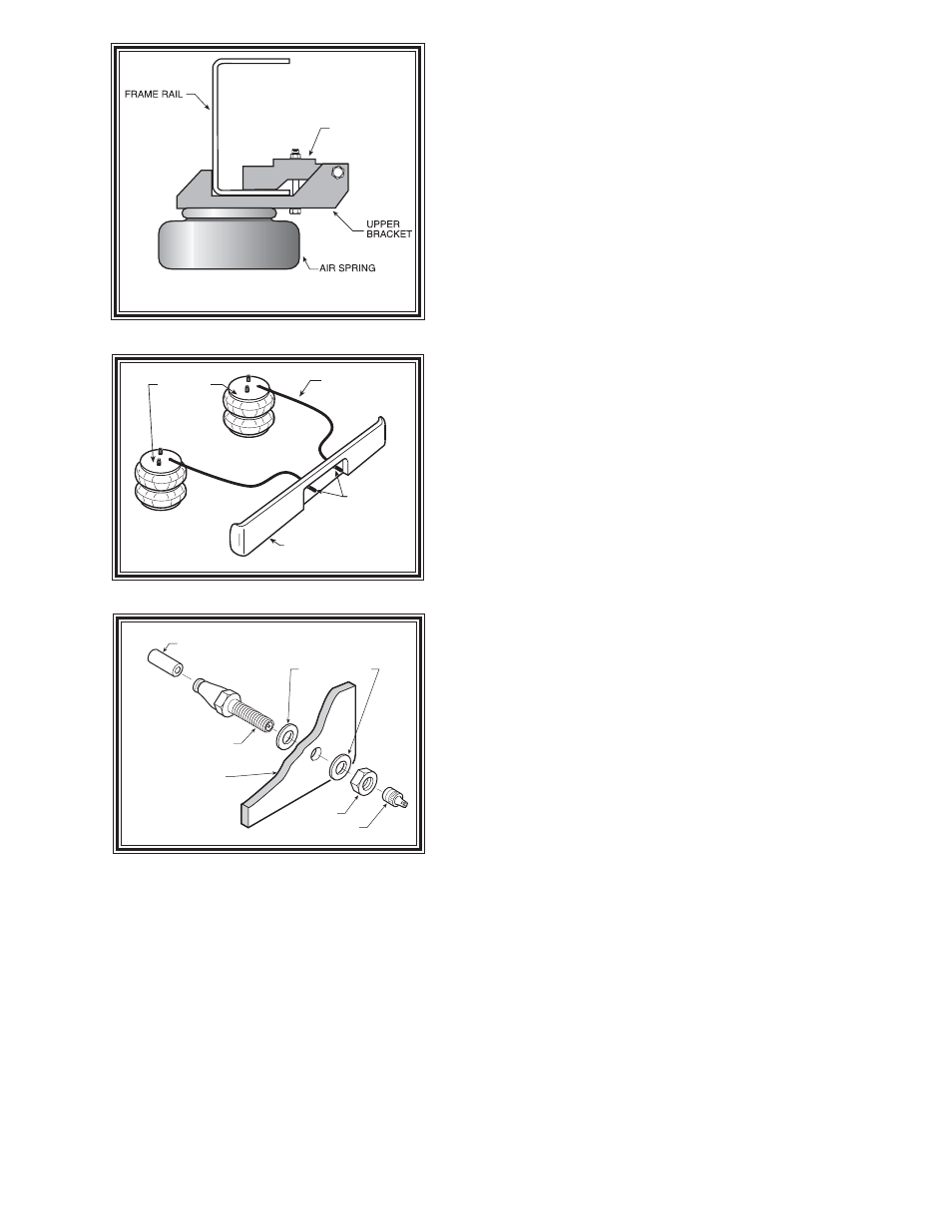
UPPER
BRACKET
CLAMP
AIR HOSE
INFLATION
VALVES
BUMPER
AIR
SPRINGS
S
TEP
1 - P
REPARE
THE
VEHICLE
Make sure that the vehicle is on a solid level surface. Take
necessary safety precautions such as using wheel chocks when
working under your vehicle. This vehicle does not have to be
jacked up to install the kit. Remove the positive battery cable.
S
TEP
2 - P
REASSEMBLE
THE
RIDE
-
RITE
KIT
Select one air helper spring from your kit and an upper
bracket. Align the mounting holes on the air spring with the holes
on the upper bracket making sure the air inlet hole can be seen
through the large hole in the upper bracket. See Figure "A". Use
the 3/8"-16 flange nuts to secure the upper bracket to the air
spring. Install the air fitting as shown in Figure "A". Tighten the
air fitting securely to engage the orange thread sealant.
Select one upper bracket clamp and attach it to the upper
bracket using two of the 3/8"-16 x 1" hex bolts and hex nuts.
Tighten the hardware finger tight. See Fighure "A".
Select one lower bracket as shown in Figure "A". Insert two
of the 3/8"-16 x 2-1/2" carriage bolts into the square holes in the
lower bracket. Next, fasten the lower bracket to the air helper
spring using one 3/8"-16x3/4" flange bolt. Aling the air spring
and lower bracket so the air inlet will be on the outside of the
frame. See Figure "A".
S
TEP
3 - A
TTACH
PRE
ASSEMBLY
TO
THE
VEHICLE
Position the assembly on the driver's side leaf stack, just
forward of the axle, as shown in Figure "A". Slide the assembly
as far back towards the axle as possible. The upper bracket will
be positioned under the frame so that the air inlet is on the outside
of the frame, and the clamp will be on the inside of the frame. See
Figure "B".
Install one of the bracket straps onto the carriage bolts from
under the spring stack and attach it with two of the 3/8"-16 flange
lock nuts.
Install two of the 3/8"-16 x 5" hex bolts from the bottom of
the upper bracket into the upper bracket clamp and fasten with
two 3/8"-16 flange lock nuts. See figures "A" & "B". Tighten the
3/8"-16 flange lock nuts on the 1" hex bolts that were installed
in the previous step.
S
TEP
4 - I
NSTALLATION
OF
THE
PASSENGER
'
S
SIDE
ASSEMBLY
Follow steps 1-4, reversing any orientations, for assembly and installation of the passenger's side.
S
TEP
6 - I
NSTALL
THE
AIR
LINE
AND
THE
INFLATION
VALVE
Uncoil the air line tubing and cut it into two equal lengths. DO NOT FOLD OR KINK THE TUBING. Try
to make the cut as square as possible. Insert one end of the tubing into the elbow fitting installed in the top
of the air helper spring. Push the tubing into the fitting as far as possible refer to Figure "A".
Select a location on the vehicle for the air inflation valves. The location can be on the bumper or the body
of the vehicle, as long as it is in a protected location so the valve will not be damaged, but maintain accessibility
for the air chuck see Figure "C". Drill a 5/16" hole and install the air inflation valve using two 5/16" flat
washers per valve as supports see Figure "D". Run the tubing from the air helper spring to the inflation valve,
routing it to avoid direct heat from the engine, exhaust pipe, and away from sharp edges. Thermal sleeves
have been provided for these conditions. If a thermal sleeve is required simply slide the sleeve over the air
line tubing to the location requiring protection. The air line tubing should not be bent or curved sharply as
it may buckle. Secure the tubing in place with the nylon ties provided. Push the end of the air line tubing into
the inflation valve as illustrated see Figure "D".
Figure "B"
AIR LINE
PUSH-TO-CONNECT
INFLATION VALVE
FLAT WASHER
HEX NUT
VALVE CAP
BODY OF
VEHICLE
Figure "D"
Figure "C"