1 - p, 2 - u, 3 - b – Rite-Ride 2061 User Manual
Page 3
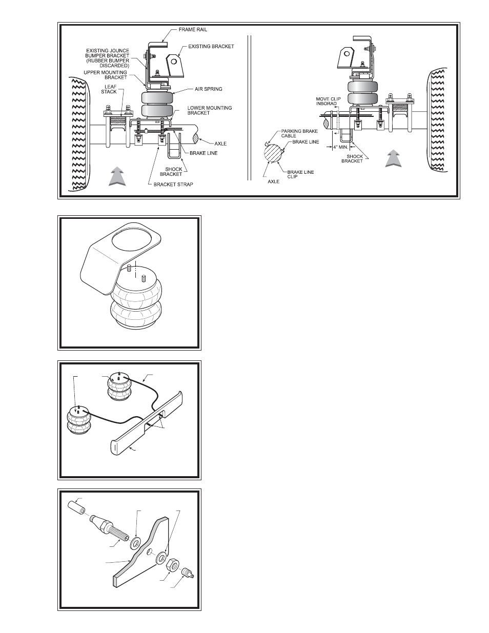
DRIVER'S SIDE
FRONT
FIGURE "B"
FIGURE "C"
S
TEP
1 - P
REPARE
THE
VEHICLE
Remove the positive battery cable. With the vehicle on a solid, level surface
chock the front wheels. Raise the vehicle by the axle and remove the rear wheels.
After the removal of the wheels lower the vehicle so the axle rests on jack stands
rated to support your vehicles weight.
Your vehicle is equipped with rubber jounce bumpers. The bumpers are
attached to the frame directly above the axle. Remove these bumpers by unbolting
from the inside of the frame flange. This bumper will not be reused with this kit.
S
TEP
2 - U
SE
OF
THE
HEAT
SHIELD
Some vehicles may require the use of a heat shield. The shield is used to deflect
heat from the air spring. A heat shield should be used if the distance between the
exhaust pipe and the air spring is approximately 6" or less. The heat shield is
mounted between the upper bracket and the upper plate of the air spring see Figure
"C". Position the shield directly between the closest heat source and the air spring.
Ensure that the heat shield will not interfere with the normal operation of the air
spring or the vehicle's suspension. Do not position the face of the shield directly
over the axle, as it may contact the axle on full suspension compression.
S
TEP
3 - B
RACKET
AND
AIR
SPRING
ASSEMBLY
This kit contains two different upper brackets, one for the left side and one for
the right side. Preassembly will begin with the left (driver's) side of the vehicle.
All pictures depict the installation on the left side unless noted otherwise. Start
by selecting the upper bracket for the left side see Figure "A". Install one
3/8" -16 x 3" carriage bolt into the upper bracket see Figure "A". Next, select one
of the air springs and install the push-to-connect air fitting in the top threaded hole
in the air spring and tighten securely. Thread sealant has been pre-applied to the
threads of the fitting so no additional sealant is required. Secure the upper bracket
to the air spring by using 3/8" -16 flanged lock nuts. Check to make sure that the
carriage bolt is still seated properly in the recessed square hole of the upper
bracket. Next, select a lower bracket and insert the carriage bolts into the square
holes. Secure the lower bracket to the air spring assembly using 3/8" -16 flanged
lock nuts see Figures "A" & "B". The lower bracket is the same for the left and
right sides. Double-check the orientation of both brackets before attempting
installation.
HEAT SHIELD
FRONT
PASSENGER'S SIDE
AIR HOSE
INFLATION
VALVES
BUMPER
AIR
SPRINGS
FIGURE "D"
FIGURE "E"
AIR LINE
PUSH-TO-CONNECT
INFLATION VALVE
FLAT WASHER
HEX NUT
VALVE CAP
BODY OF
VEHICLE