Rite-Ride 2446 User Manual
Page 3
STEP 1 — PREPARE THE VEHICLE
Your vehicle is equipped with rubber jounce bumpers attached to the
frame directly above the axle. Remove these bumpers by un-bolting
from the inside of the frame flange.These bumpers will not be re-used
with this kit.
STEP 2 — UPPER BRACKET INSTALLATION
Insert the 3/8"-16 x 2-1/2" flat head bolt into the upper bracket and then
slide the spacer bracket over the bolt. Install the upper bracket onto the
frame. Make sure that no part of the vehicle’s wiring will be pinched
between the upper bracket and the frame. Tighten the 3/8"-16 flat head
bolt with a 3/8"-16 flange nut and the large 3/8" washer. Install the
3/4"-16 x 3” hex bolt thru the existing hole in the frame rail and upper
bracket. Secure the 3/4" bolt with a 3/4" flat washer, 3/4" lock washer,
and 3/4" hex nut.
If you have existing hitch hardware, the 3/4" bolt should be long
enough to extend thru the upper bracket, truck frame and the hitch
brackets (if present). Be sure to use at least one of the large flat wash-
ers and lock washer before putting the 3/4" nut onto the bolt. Finally,
the emergency brake cable will have to be tie-wrapped out of the way
using the hole provided in the upper bracket. See Figure “A”.
STEP 3 — LOWER BRACKET INSTALLATION
Select one air helper spring and lower bracket. Install two 3/8"-16 X
10" carriage bolts as shown in Figure “A”. Fasten the air spring to
the lower bracket using two 3/4” hex bolts. See Figure “A”. Remove
the flanged hex bolt from the sway bar mount on top of the axle. Next
attach the lower bracket assembly to the axle using the carriage bolts,
bracket clamp, and two 3/8"-16 flange nuts. Reinstall the bolt removed
from the sway bar mount. See Figure “A”.
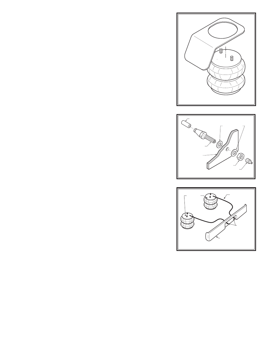
STEP 4 — AIR SPRING INSTALLATION
The heat shield will be used on the right side of the truck where the
exhaust pipe is closest to the air spring. It is placed between the upper
bracket and the top of the air spring. The top of the air spring has a
alignment pin which will be put into the smaller hole in the upper bracket
towards the front of the truck on both sides. When the air spring is in
place and properly lined up, place the internal tooth lock washer and
the 3/4” hex nut onto the stud of the air spring. On the right side move
the heat shield into alignment before tightening the nut on the air spring.
Make sure the heat shield will not interfere with the normal operation
of the air spring or the vehicle’s suspension. Do not position the face
of the shield directly over the axle, as it may contact the axle on full
suspension compression. See Figure “B”. Install the air fitting into
the stud of the air spring. Tighten the air fitting securely to engage the
orange thread sealant.
STEP 5 — AIR LINE INSTALLATION
Uncoil the air tubing and cut it into two equal lengths.
DO NOT FOLD
OR KINK THE TUBING. Try to make the cut as square as possible.
Insert one end of the tubing into the elbow fitting installed in the top of
the air helper spring. Push the tubing into the fitting as far as possible.
Select a location on the vehicle for the air inflation valves. This can be
on the bumper or the body of the vehicle, as long as it is protected so
the valves will not be damaged. Drill a 5/16" hole and install the air infla-
tion valve using two 5/16" flat washers per valve as supports. Route the
tubing from the air helper spring to the inflation valve, avoiding direct
heat from the engine, exhaust pipe, and away from sharp edges. The
air line tubing should not be bent or curved sharply as it may buckle
with time. Secure the tubing in place with the nylon ties provided. Push
the end of the air line tubing into the inflation valve as far as possible.
See Figures “C” & “D”.
Figure “B”
HEAT SHIELD
AIR LINE
PUSH-TO-CONNECT
INFLATION VALVE
FLAT WASHER
HEX NUT
VALVE CAP
BODY OF
VEHICLE
Figure “C”
Figure “D”
AIR HOSE
INFLATION
VALVES
BUMPER
AIR
SPRINGS