1 - p, 2 - p, 3 - a – Rite-Ride 2378 User Manual
Page 3: 4 – m, 5– a
PASSENGER’S SIDE
AIR LINE
PUSH-TO-CONNECT
INFLATION VALVE
FLAT WASHER
HEX NUT
VALVE CAP
BODY OF
VEHICLE
Figure "B"
S
TEP
1 - P
REPARE
THE
VEHICLE
With the vehicle on a solid, level surface
chock the front wheels. Raise the vehicle
by the axle and remove the rear wheels.
After the removal of the wheels, lower the
vehicle so the axle rests on jack stands rated
for your vehicles weight. Remove the nega-
tive battery cable.
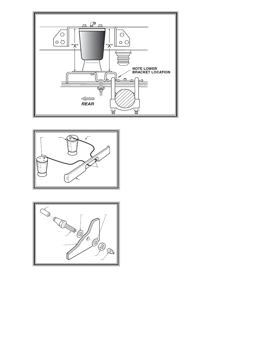
THE “X” DIMENSION.
Throughout this manual we refer to
an “X” dimension. This is the initial,
un-inflated overall height of the air
spring. Both right and left sides should
be installed at the same height. The
“X” dimension on this air spring is
7"to 8".
The air spring may require
some stretching to achieve this di-
mension.
S
TEP
2 - P
RE
-
ASSEMBLE
THE
KIT
Select one air helper spring from your kit. Install the upper bracket
by aligning the three holes on the air spring with the holes on the upper
bracket. Fasten the upper bracket to the air spring using the 3/8" x
3/4" flange hex bolts as shown in Figure “A”. Install the air fitting
as shown in Figure “A”. Tighten the air fitting to make contact with
the Teflon ring and then tighten an additional 1/2 turn. No thread
sealant is needed. Insert the two 3/8"x 4 1/2" carriage bolts into the
lower bracket. Next, attach the lower bracket and disk to the air
spring using the 3/8"x 3/4" flange hex bolt (see Figure “A”). Note:
Finger tighten the bolt securing the lower bracket and disk allowing the
air spring to move freely. This will be tightened after alignment
in Step 6.
S
TEP
3 - A
TTACH
LOWER
BRACKET
TO
LEAF
SPRING
Place the assembly on the right side on top of the leaf spring stack
rearward of the axle (see Figure “A” and “B”). Attach the lower
bracket to the leaf stack using the 3/8" x 4 1/2" carriage bolts (installed
earlier), the bracket strap, and the flange lock nuts as shown in Figure
“A” and “B”. (Tighten to 15-20 ft. lbs.)
S
TEP
4 – M
ARK
AND
DRILL
HOLES
IN
THE
FRAME
RAIL
Visually align the air spring so that it is vertically straight and the
upper and lower brackets are parallel. Place the upper bracket so the
top of the bracket is parallel with the top of the frame rail. See Figure
“A” and “B”. Check the “X” dimension on both sides of the air
spring, these dimensions should be the same (refer to Figure “B”).
Before drilling the holes make sure all electrical, brake and fuel lines are cleared from the path of the drill. In order
to prevent any damage to these lines it is recommended that a piece of wood be placed between the frame rail and the
existing lines during drilling. With the air spring assembly in place, mark the upper left hole with a center punch. Drill
the hole using a 3/8" drill bit.
S
TEP
5– A
TTACHING
THE
UPPER
BRACKET
Once the hole has been drilled, attach the upper bracket using the 3/8"-16 x 4 1/2" hex bolt, large flat
washer, and the flange hex nut to the frame rail (finger tight). This will allow you to adjust the upper bracket. Once
the positioning of the upper bracket is parallel to the lower bracket and the "X" dimensions are equal, drill the
remaining three holes in the frame rail using the upper bracket as a template. Use the 3/8"-16 x 4 1/2" hex bolts,
large flat washers, and flange hex nuts to fasten the upper bracket to the frame rail. See Figure "A". Once the upper
bracket is secure, align the bottom of the air spring side to side to ensure that it is vertical. Tighten the bolt
securing the lower bracket to the air spring.
AIR HOSE
INFLATION
VALVES
BUMPER
AIR
SPRINGS
Figure "C"
Figure "D"