Rite-Ride 2169 User Manual
Page 3
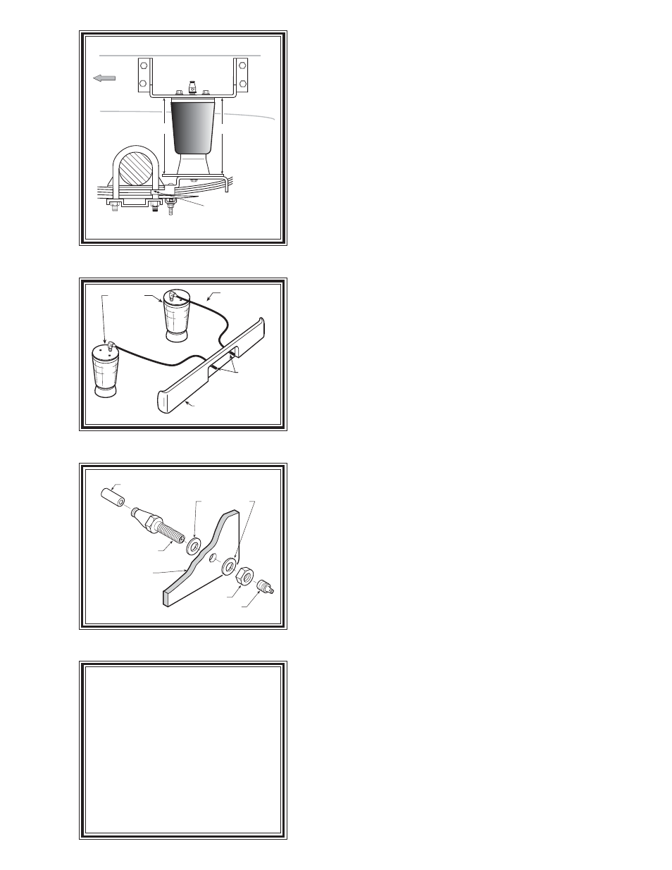
NOTE LOWER
BRACKET LOCATION
X = 7.25
“X”
“X”
DRIVER’S SIDE
FRONT
Figure "B"
Figure "D"
AIR LINE
PUSH-TO-CONNECT
INFLATION VALVE
FLAT WASHER
HEX NUT
VALVE CAP
BODY OF
VEHICLE
Figure "C"
AIR HOSE
INFLATION
VALVES
BUMPER
AIR
SPRINGS
NOTE:
Once the air helper springs
are installed, it is recommended that
the vehicle not be lifted by the frame,
as over-extension may occur, re-
sulting in damage to the air helper
springs. However, should it be-
come necessary to raise the vehicle
by the frame, deflate both air helper
springs completely.
S
TEP
1 - P
REPARE
THE
VEHICLE
With the vehicle on a solid, level surface chock the front wheels.
Raise the vehicle by the axle and remove the rear wheels. After the
removal of the wheels lower the vehicle so the axle rests on jack stands
rated for your vehicles weight. Remove the positive battery cable.
S
TEP
2 - P
REASSEMBLE
THE
RIDE
-
RITE
KIT
Select one air helper spring from your kit. Install the upper bracket
by aligning the threaded holes on the air spring with the small holes
on the upper bracket. Fasten the upper bracket to the air spring using
the 3/8"-16 x 3/4" flanged hex bolt as shown in Figure "A". Install the
air fitting as shown in Figure "A". Tighten the air fitting securely to
engage the orange thread sealant. Insert the two 3/8"-16 x 4 1/2"
carriage bolts into the lower bracket. Next, attach the lower bracket
and disk to the air spring using the 3/8"-16 x 3/4" flanged hex bolt
finger tight see Figure "A". Refer to Figure "A" & "B" for proper
orientation of the lower bracket.
S
TEP
3 - A
TTACH
LOWER
BRACKET
TO
LEAF
SPRING
Place the assembly on the passenger’s side on top of the leaf spring
stack behind the axle (see Figure "A" and "B"). Attach the lower
bracket to the leaf stack using the 3/8"-16 x 4 1/2" carriage bolts installed
earlier and bracket strap as shown in Figure "A" and "B". Note that the
hook on the lower bracket will capture the "U"-bolt. The bracket strap is
used to clamp the lower bracket to the leaf stack (see Figure "A" and "B").
S
TEP
4 - M
ARK
AND
DRILL
HOLES
IN
THE
FRAME
RAIL
Visually align the air spring so that it is vertically straight and the
upper and lower brackets are parallel. (Note: The upper bracket
should not exceed the top surface of the frame rail.) see Figure "A"
and "B". Check the "X" dimension on both sides of the air spring, this
dimension should be approximately 7.25" on both sides refer to
Figure "B". With the air spring assembly in place, mark the upper
left hole with a center punch. Drill the hole using a 7/16" drill bit.
Before drilling the holes make sure all electrical, brake and fuel
lines are cleared from the path of the drill. In order to prevent any
damage to these lines it is recommended that a piece of wood be placed
between the frame rail and the existing lines when drilling.
S
TEP
5 - A
TTACHING
THE
UPPER
BRACKET
Once the hole has been drilled attach the upper bracket using the
3/8"-16 x 1 1/2 inch hex bolt, large flat washer and the flanged hex nut
to the frame rail (finger tight). This will allow you to adjust the
location of the upper bracket. Once the positioning of the upper
bracket is parallel with the lower bracket and the "X" dimensions are
equal, drill the remaining three holes in the frame rail using the upper
bracket as a template. Use the 3/8"-16 x 1 1/2 inch hex bolts, large flat
washers and the flanged hex nuts to fasten the upper bracket to the
frame rail refer to Figure "A". Tighten the air spring to the lower
bracket using a 9/16" open end wrench.
S
TEP
6 - I
NSTALLATION
OF
THE
PASSENGER
'
S
SIDE
ASSEMBLY
Follow steps 1-5 for assembly and installation of the passenger's side
assembly. Note, reverse any orientations for the passenger side
installation.