1 - p, 2 - p, 3 - i – Rite-Ride 2286 User Manual
Page 3: 4 - i, 5 - i
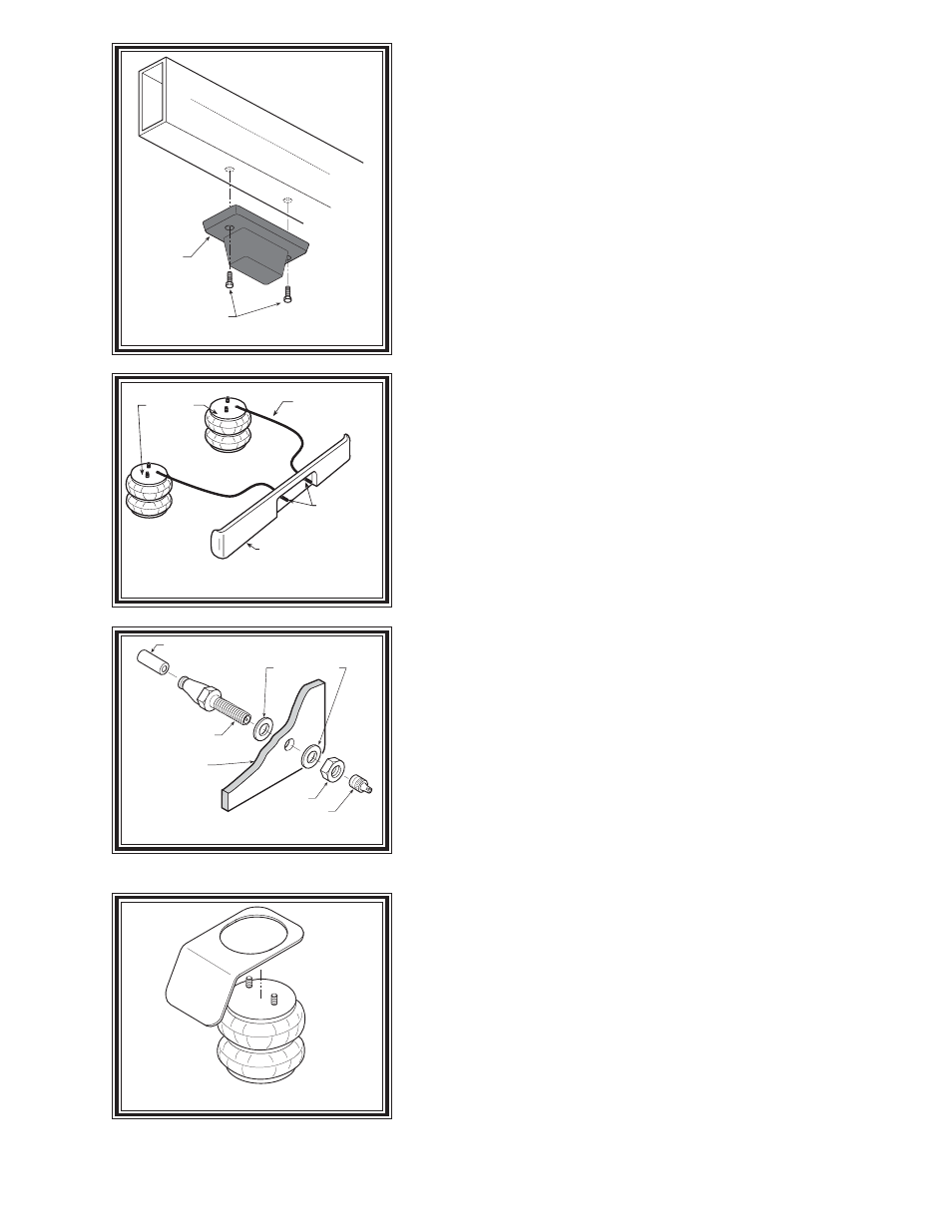
JOUNCE
BUMPER
SAVE FOR
LATER USE
Figure "B"
Figure "D"
S
TEP
1 - P
REPARE
THE
VEHICLE
Installation of this kit is possible without raising the vehicle. To achieve
greater clearances while installing this kit, it is recommended to raise the vehicle.
Chalk the front wheels and raise the vehicle, using a lift or platform jack rated
for your vehicle weight, until the rear wheels are off the ground. Remove the rear
wheels. Lower the vehicle onto jack stands rated for your vehicle weight. (Do
not use wood or concrete blocks to support the weight of your vehicle.) Remove
the negative battery cable.
S
TEP
2 - P
RE
-
ASSEMBLE
THE
KIT
Install the elbow fitting into the air spring. Tighten the air fitting securely to
engage the orange thread sealant. Position the elbow so that it points
toward the anticipated location of the air inflation valve see Figures “A” &
“C”. Assemble upper air spring bracket to air spring as shown in Figure
"A". (Sandwich the heat shield between the upper air spring bracket and the
air spring on the passenger side.) Attach the upper bracket using two 3/8"-16
hex head flange nuts. Attach the lower bracket to the air spring by using a
3/8"-16 X 3/4" hex head flange bolt.
Cut a 6” piece of air line tubing making the cut as square as possible. Insert
tubing into inflation valve until it stops completely. Compress air helper spring
assembly letting air escape from air spring. Insert open end of 6” air line tubing
into air spring fitting completely while air spring is compressed (this will keep the
air spring collapsed).
S
TEP
3 - I
NSTALLING
THE
ASSEMBLY
TO
THE
VEHICLE
Remove the jounce bumper from the bottom of the truck frame and retain the
jounce bumper bolts for later use, refer to Figure "B". Place the assembly on
the vehicle as shown in Figure "A". Remove the 6" piece of air line tubing from
the air spring by pressing the brass collar toward the fitting and simultaneously
pulling the tubing out of the fitting. The air spring will expand to it's original
dimensions. Attach the upper bracket to the truck frame using the jounce bumper
bolts removed earlier as illustrated in Figure "A". Align slots on the outside of
the lower bracket with the "U" bolt as shown in Figure "A". Insert the carriage
bolts into the lower bracket. Place the bracket clamp in place as shown in Figure
"A" and attach with two 3/8"-16 flange nuts. Insert the bail clamp from the outside
of the leaf stack and through the lower bracket and attach with 3/8"-16 flange nuts,
see Figure "A".
S
TEP
4 - I
NSTALLATION
OF
THE
PASSENGER
'
S
SIDE
ASSEMBLY
Follow steps 2-3 with reverse orientations for assembly and installation of the
passenger's side assembly. Install heat shield between the upper bracket and the
air spring as shown in Figure "A". Note: The use of a heat shield is required on
the passenger side of the vehicle, see Figures "A" and "E". The heat shield will
mount between the upper bracket and the air spring. Angle the heat shield so it
will fall halfway between the air spring and the closest point on the exhaust. Be
sure the heat shield will not contact any other components as the suspension
compresses (ie. brake lines, shock absorbors, lower bracket, axle, etc).
S
TEP
5 - I
NSTALL
THE
AIR
LINE
AND
INFLATION
VALVE
Uncoil the airline tubing and cut it into two equal lengths. DO NOT FOLD
OR KINK THE AIRLINE TUBING. Try to make the cut as square as possible.
Insert one end of the airline tubing into the air fitting installed in the top of the
air helper spring. Push the airline tubing into the fitting as far as possible, refer
to Figure "A".
Select a location on the vehicle for the air inflation valves. The location can
Figure "C"
AIR HOSE
INFLATION
VALVES
BUMPER
AIR
SPRINGS
AIR LINE
PUSH-TO-CONNECT
INFLATION VALVE
FLAT WASHER
HEX NUT
VALVE CAP
BODY OF
VEHICLE
Figure "E"
HEAT SHIELD