1 - p, 2 - a, 3 - p – Rite-Ride 2220 User Manual
Page 3: 4 - i, 5 - i
AIR HELPER
SPRING
LOWER BRACE
LOWER BRACKET
BRACKET STRAP
LEAF STACK
UPPER BRACKET
FRAME RAIL
DRIVER'S SIDE
FRONT
AXLE
BOLTS FROM
JOUNCE BUMPER
REMOVAL
S
TEP
1 - P
REPARE
THE
VEHICLE
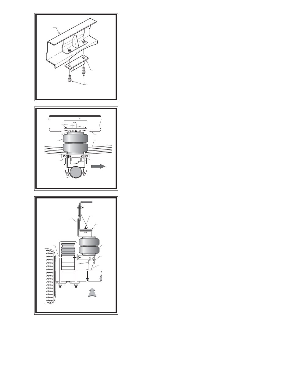
With the vehicle on a solid level surface, chock the front wheels. This vehicle does not
have to be jacked up to install this kit. Remove the negative battery cable. Remove the jounce
bumpers by unbolting them from the frame see Figure "B". The jounce bumpers will not
be reused in this installation. Save the hex bolts used to secure the jounce bumper. They
will be used later in this installation.
S
TEP
2 - A
DJUST
THE
LOWER
BRACE
Select the lower bracket and lower brace stamped "L" from your kit. Due to the variations
in the jounce bumper pads, there are three different variations in which the lower bracket
and lower brace can be bolted together see Figure "C". The lower brace should rest against
the axle housing. To determine which position to use, hold the lower bracket and the lower
brace in place together. The lower bracket should be as level as possible. Insert the
3/8" -16 x 1" bolts through the holes in the lower bracket that align with the holes in the lower
brace.
S
TEP
3 - P
REASSEMBLE
THE
KIT
Note: The left and right brackets are stamped with the letters "L" or "R". ("L" for
left and "R" for right)
Select the left side upper bracket and one air spring from your kit. Install the brass air
fitting into the threaded hole (finger tight). Next, attach the upper bracket to the air spring
using the 3/8" -16 flange lock hex nuts. Tighten the air fitting to engage at least two threads
with the pre-applied orange thread sealant. Select the lower left bracket and lower left brace
(assembled in Step 2) see Figures “A” & “C”. Fasten the lower left brace to the lower left
bracket using the 3/8"-16 x 1" hex bolts (inserted in Step 2) and flanged hex nuts see Figures
“A” & “C”. Attach the lower bracket assembly to the air spring using the 3/8"-16 x 3/4"
flanged hex bolt (finger tight).
S
TEP
4 - I
NSTALL
THE
ASSEMBLY
TO
THE
VEHICLE
Place the assembly on the vehicle by installing the upper bracket so that it lays against
the outside of the frame rail see Figure "D". The lower bracket will set over the top of the
jounce bumper pad with the lower brace under the jounce bumper pad see Figure "A". The
lower bracket brace will set on top of the axle housing. Push the lower bracket toward the
leaf spring until it rests against the leaf spring U-bolts.
Match the upper bracket to the existing holes in the frame rail left by the removal of
the jounce bumper. Using the hex bolts from the jounce bumper removal, fasten the upper
bracket to the bottom of the frame rail. The tab on the upper bracket will align with an existing
hole on the outside of the frame rail. Using a 1/4" -20 flanged hex nut and 1/4" -20 x 1" hex
bolt, fasten the upper bracket to the outside of the frame rail see Figure “A”.
Tighten the 3/4" -16 x 3/4" flanged hex bolt to secure the lower bracket to the air helper
spring. Next, install the bail clamp around the casting. Insert the bail clamp through the
holes in the lower bracket see Figure "A". Install 3/8" -16 flanged hex nuts and draw the
lower bracket against the leaf spring U-bolts. Next, attach the bracket straps to the lower
left brace. Using two 3/8" -16 x 3" carriage bolts, attach the bracket straps to the lower left
bracket brace, making sure that the bracket straps are holding the assembly securely on the
axle housing see Figure "A".
To provide adequate clearance, the parking brake cable must be repositioned so that it
does not contact the air spring. Remove the factory clip between the parking brake cable
and wire harness and attach the supplied P-clip to the lower bracket see Figure "E". The
remaining wire harness can be tied to the parking brake cable with the provided nylon ties
see Figure "E".
Make sure that the parking brake cable and wire harness will not contact the air spring
or other undercarriage components.
S
TEP
5 - I
NSTALL
THE
PASSENGER
'
S
SIDE
ASSEMBLY
To install the passenger's side, or right side assembly, follow Steps 2-4 while reversing any orientations. Use the brackets and brace stamped
"R".
Note: The use of a heat shield is required on the passenger's side of the vehicle refer to Figure "F". The heat shield will mount between
the upper bracket and the air spring. Adjust the heat shield so it will fall halfway between the air spring and the closest point on the exhaust.
Be sure that the heat shield will not contact any vehicle component under full suspension compression (brake lines, shock absorbers, lower bracket
and brace assembly).
FIGURE "B"
FIGURE "C"
FRAME RAIL
UNBOLT AND REMOVE
JOUNCE BUMPER
RETAIN JOUNCE
BUMPER BOLTS
JOUNCE BUMPER
FIGURE "D"
LOWER
BRACKET
LOWER
BRACE
BAIL CLAMP
DRIVER'S SIDE
FRONT
UPPER BRACKET
AIR
SPRING
FRAME RAIL
JOUNCE BUMPER
BOLT