Rite-Ride 1004 User Manual
Page 3
STEP 3—INSTALLING THE AIR LINE AND
INFLATION VALVE
Uncoil the air line tubing and cut it into two equal lengths.
DO NOT
FOLD OR KINK THE TUBING. Try to make the cut as square as pos-
sible. Insert one end of the tubing into the straight fitting installed into
the Level-Rite. Push the tubing into the fitting as far as possible,
see
Figure “B”.
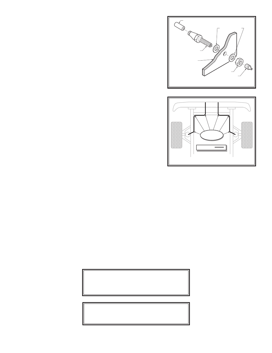
Select a location on the vehicle for the air inflation valves. The loca-
tion can be on the bumper or the body of the vehicle, as long as it is
in a protected location so the valve will not be damaged, but maintain
accessibility for the air chuck,
see Figure “C”. Drill a 5/16" hole and
install the air inflation valve using two 5/16" flat washers per valve as
supports,
see Figure “C”. Run the tubing from the air helper spring to
the inflation valve, routing it to avoid direct heat from the engine, exhaust
pipe, and away from sharp edges. Thermal sleeves have been provided
for these conditions. If a thermal sleeve is required simply slide the
sleeve over the air line tubing to the location requiring protection. The
air line tubing should not be bent or curved sharply as it may buckle.
Secure the tubing in place with the nylon ties provided. Push the end of
the air line tubing into the inflation valve as illustrated,
see Figure “C”.
STEP 4— CHECK THE SYSTEM
Once the inflation valves are installed inflate the Air Over shocks to
70
psi and check the fittings for air leaks with an applied solution of soap
and water. If a leak is detected at a tubing connection then check to
make sure that the tube is cut as square as possible and that it is pushed
completely into the fitting. The tubing can easily be removed from the
fittings by pushing the collar towards the body of the fitting and then
pulling out the tube. If a leak is detected where the brass fitting screws
into the shock, remove the tubing by pushing the collar towards the body
of the fitting and then pulling out the tube, then screw the brass fitting
into the shock one additional turn. Reinstall the tubing and re-inflate
the air springs and check for leaks as noted above.
This now completes the installation. Install the wheels and torque
the lug nuts to the manufactures specifications. Raise the front of the
vehicle, remove the jack stands, and lower the vehicle back onto the
ground.
FOR BEST RIDE use only enough air pressure in the air helper
springs to level the vehicle when viewed from the side (front to rear).
This amount will vary depending on the load, location of load, condition
of existing suspension and personal preference.
AIR LINE
PUSH-TO-CONNECT
INFLATION VALVE
FLAT WASHER
HEX NUT
VALVE CAP
BODY OF
VEHICLE
Figure “B”
Figure “C”
NOTE:
MIN PRESSURE
10 PSI
MAX PRESSURE (LOADED)
100 PSI
NOTE:
DO NOT remove the air spring
assembly from the shock. This will cause
damage to the product and void the warranty.
NYLON TIES
AIR LINE