Rite-Ride 2451 User Manual
Page 3
PASSENGER
PLASTIC SHIELD (PASSENGER SIDE)
MUST BE TRIMMED
N
OTE
:
Please read thorough this manual completely before
installing the air spring kit on your vehicle.
S
TEP
1 - P
REPARE
THE
VEHICLE
With the vehicle on a solid, level surface chock the front wheels.
Remove the negative battery cable.
S
TEP
2 - P
RE
-
ASSEMBLE
THE
KIT
Pre-assembly will begin with the left (driver's) side of the
vehicle. Select one air helper spring and one upper bracket from your
kit. Insert the large combination stud on the air spring into the large
mounting hole in the upper bracket. Make sure that the small
alignment pin inserts into the smaller hole in the upper bracket.
Fasten the upper bracket to the air spring by installing the 3/4" hex
nut and 3/4" lock washer on the air spring's combination stud. Next,
install the air fitting into the air inlet in the combination stud. Tighten
the air fitting securely to engage the orange thread sealant. Position the
fitting to point to the anticipated location of the air inflation valves, see
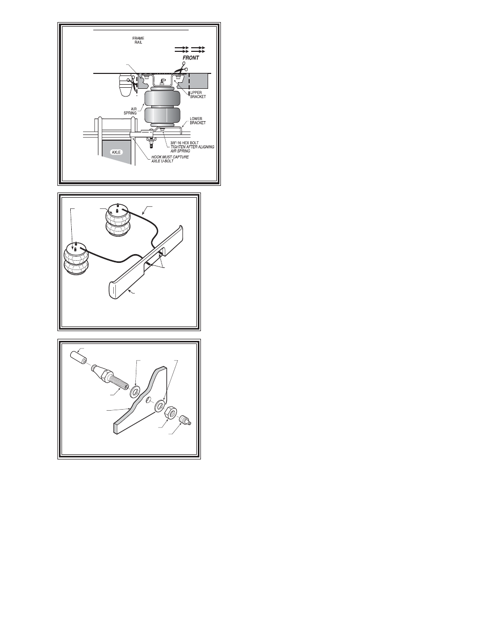
Figure "A" & "C". No thread sealant is needed. Select one lower
bracket from you kit. Fasten the air spring to the lower bracket using a
3/8"-16 X 3/4" flanged hex bolt in the hole in the lower bracket, see Figure
"A".
S
TEP
3 - I
NSTALLING
THE
ASSEMBLY
TO
THE
VEHICLE
Remove the two existing blots on the bottom of the frame rail, just
forward of the axle. Next, attach the upper bracket to the frame rail using
the bolts just removed, see Figure "A". On the driver's side frame rail,
there is a flexible line that may come into contact with the air spring.
Bend the line's retaining bracket up and away for the air spring.
Next, insert the 3/8"-16 x 3 1/2" carriage bolts through the square holes
in the lower bracket. The lower bracket should be aligned over the leaf
spring with the hook capturing the leaf spring U-bolt, see Figure "B".
The carriage bolts should be straddling the leaf stack. Slide the bracket
strap on the carriage bolts and secure it with two 3/8"-16 flanged lock nuts,
see Figure "A". Once the assembly is in place, ensure that there is at
least 1/2" of clearance around the air spring.
S
TEP
4 - I
NSTALLATION
OF
THE
PASSENGER
'
S
SIDE
ASSEMBLY
Follow steps 1-3 with reverse orientations for assembly and installation
of the passenger's side assembly. On the passenger side, there is a
plastic shield attached to the frame rail. This must be trimmed for
installation of the air spring. See Figure "B".
S
TEP
5 - I
NSTALL
THE
AIR
LINE
AND
INFLATION
VALVE
Uncoil the airline tubing and cut it into two equal lengths. DO NOT FOLD OR KINK THE AIRLINE TUBING.
Try to make the cut as square as possible. Insert one end of the airline tubing into the air fitting installed in the top
of the air helper spring. Push the airline tubing into the fitting as far as possible see Figure "A".
Select a location on the vehicle for the air inflation valves. The location can be on the bumper or the body of the
vehicle, as long as it is in a protected location so the valve will not be damaged, but maintain accessibility for the air
chuck see Figure "D". Drill a 5/16" hole and install the air inflation valve using two 5/16" flat washers per valve
as supports see Figure "E". Run the airline tubing from the air helper spring to the valve, routing it to avoid direct
heat from the engine, exhaust pipe, and away from sharp edges. Thermal sleeves have been provided for these
conditions. The airline tubing should not be bent or curved sharply as it may buckle. Secure the airline tubing in place
with the nylon ties provided. Push the end of the airline tubing into the inflation valve as illustrated see Figure "E".
Figure "B"
Figure "D"
Figure "C"
AIR HOSE
INFLATION
VALVES
BUMPER
AIR
SPRINGS
AIR LINE
PUSH-TO-CONNECT
INFLATION VALVE
FLAT WASHER
HEX NUT
VALVE CAP
BODY OF
VEHICLE