6 -i, 7 -i, 8 -c – Rite-Ride 2176 User Manual
Page 4
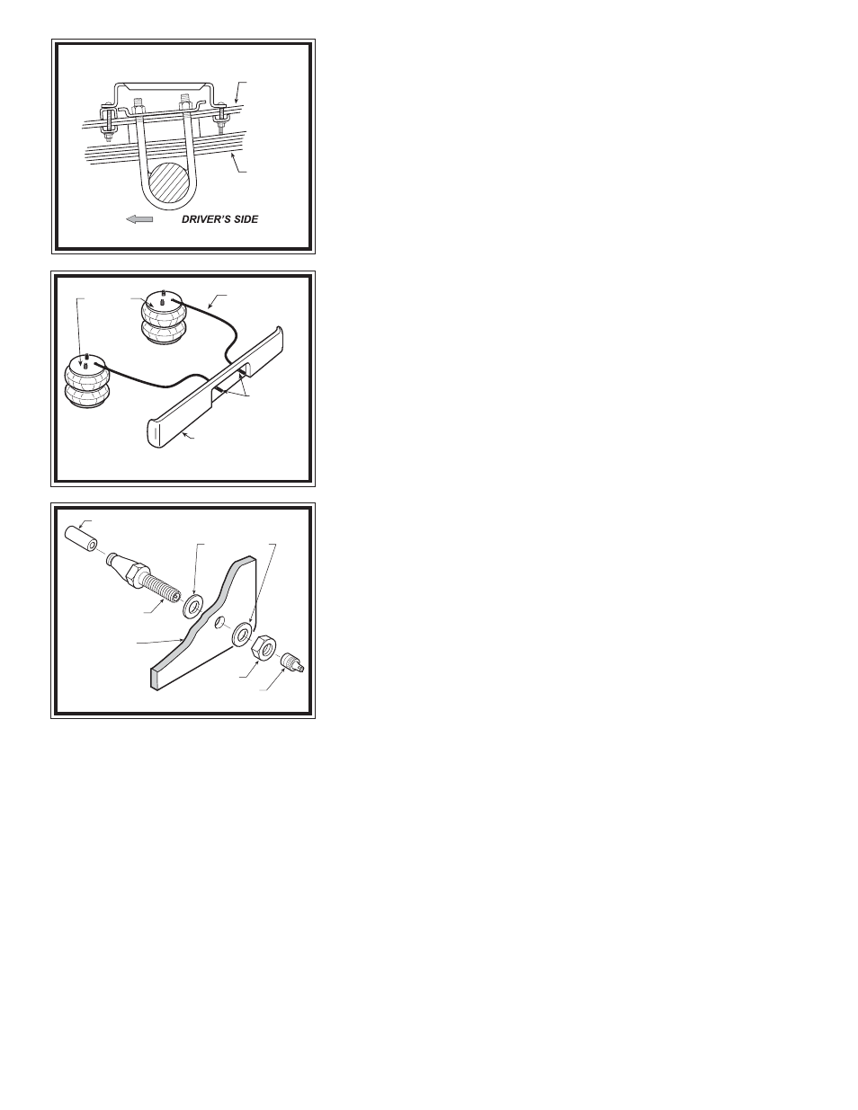
Slide the bracket straps onto the carriage bolts as to clamp the lower bracket
to the leaf stack see Figures "A" & "D". Fasten the bracket strap to the carriage
bolts using two 3/8"-16 flanged hex nuts. The F-350's will use a staggered
bracket strap (one leg is longer than the other) behind the axle see Figure "A".
Note: F-350's will clamp around the entire leaf stack, F-450's & F-550's will clamp
around the overload springs only see Figures "D" & "E". Slide the lower
bracket forward or backward to align the air spring as close to vertical as
possible. Tighten the 3/8"-16 flanged hex bolt that holds the air spring to the
lower bracket.
S
TEP
6 -I
NSTALL
THE
PASSENGER
'
S
SIDE
ASSEMBLY
Reverse any orientations when assembling and installing the right, or
passenger's, side of the vehicle. Note that the installation on the passenger's
side does not require the flat washers between the upper bracket and the frame
rail see Figure "C". The passenger's side installation will not require the
relocation of any existing hardware on the frame rail.
S
TEP
7 -I
NSTALL
THE
AIR
LINE
AND
THE
INFLATION
VALVE
Uncoil the air line tubing and cut it into two equal lengths. DO NOT FOLD
OR KINK THE TUBING. Try to make the cut as square as possible. Insert one
end of the tubing into the straight fitting installed in the top of the air helper
spring. Push the tubing into the fitting as far as possible see Figure "A".
Select a location on the vehicle for the air inflation valves. The location
can be on the bumper or the body of the vehicle, as long as it is in a protected
location so the valve will not be damaged, but maintain accessibility for the
air chuck see Figure "F". Drill a 5/16" hole and install the air inflation valve
using two 5/16" flat washers per valve as supports see Figure "G". Run the
tubing from the air helper spring to the inflation valve, routing it to avoid
direct heat from the exhaust pipe and away from sharp edges. Thermal sleeves
have been provided for these conditions. If a thermal sleeve is required,
simply slide the sleeve over the air line tubing to the location requiring
protection. The air line tubing should not be bent or curved sharply as it may
buckle. Secure the tubing to the vehicle using the provided nylon ties. Push
the end of the air line tubing into the inflation valve as far as possible see Figure
"G".
S
TEP
8 -C
HECK
THE
AIR
SYSTEM
Once the inflation valves are installed, inflate the air helper springs to 70
psi and check the fittings for air leaks. Using a spray bottle, apply a solution
of soap and water to the fittings. If a leak is detected at a airline tubing
connection then check to make sure that the airline tube is cut as square as
possible and that it is pushed completely into the fitting. The airline tubing can
easily be removed from the fittings by exhausting all the pressure in the air springs and then pushing the collar towards the body
of the fitting and then, with a pull, remove the airline tubing. Reinstall the tubing and reinflate the air springs and check for leaks
as noted above. If a leak is detected where the air fitting screws into the spring, remove the tubing then screw the elbow into the
spring 1/4 additional turn. Reinstall the tubing and reinflate the air springs and check for leaks.
This now completes the installation. Install the wheels and torque the lug nuts to the manufacturer's specification. Raise the
vehicle by the axle and remove the jack stands. Lower the vehicle to the ground. Reattach the negative battery cable and remove
the wheel chocks from the front wheels. Before proceeding, check once again to be sure you have proper clearance around the
air springs. With a load on your vehicle and the air helper springs inflated, you must have at least 1/2" clearance around the air
springs. As a general rule, the air helper springs will support approximately 50 lbs. of load for each psi of inflation pressure (per
pair). For example, 50 psi of inflation pressure will support a load of 2500 lbs. per pair of air helper springs. FOR BEST RIDE use
only enough air pressure in the air helper springs to level the vehicle when viewed from the side (front to rear). This amount will
vary depending on the load, location of load, condition of existing suspension and personal preference.
N
O T E
:
Too much air pressure in the air helper springs will result in a firmer ride, while too little air pressure will allow the air helper
spring to bottom out over rough conditions. Too little air pressure will also not provide the improvement in handling that is
possible. TO PREVENT POSSIBLE DAMAGE MAINTAIN A MINIMUM OF 5 P.S.I. IN THE AIR HELPER SPRINGS AT
ALL TIMES.
Minimum Pressure: 5psi.
Max Pressure (loaded): 100psi.
Figure "F"
PUSH-TO-CONNECT
INFLATION VALVE
BODY OF
VEHICLE
AIR LINE
FLAT WASHER
HEX NUT
VALVE CAP
Figure "G"
AIR HOSE
INFLATION
VALVES
BUMPER
AIR
SPRINGS
Figure "E"
OVERLOAD
LEAF STACK
PRIMARY
LEAF STACK
ON F-450 & F-550 MODELS, FASTEN UPPER
BRACKET TO SUSPENSION BY CLAMPING
AROUND OVERLOAD LEAF STACK
FRONT