1 - p, 2 - p, 3 - i – Rite-Ride 2252 User Manual
Page 3: 4 - i
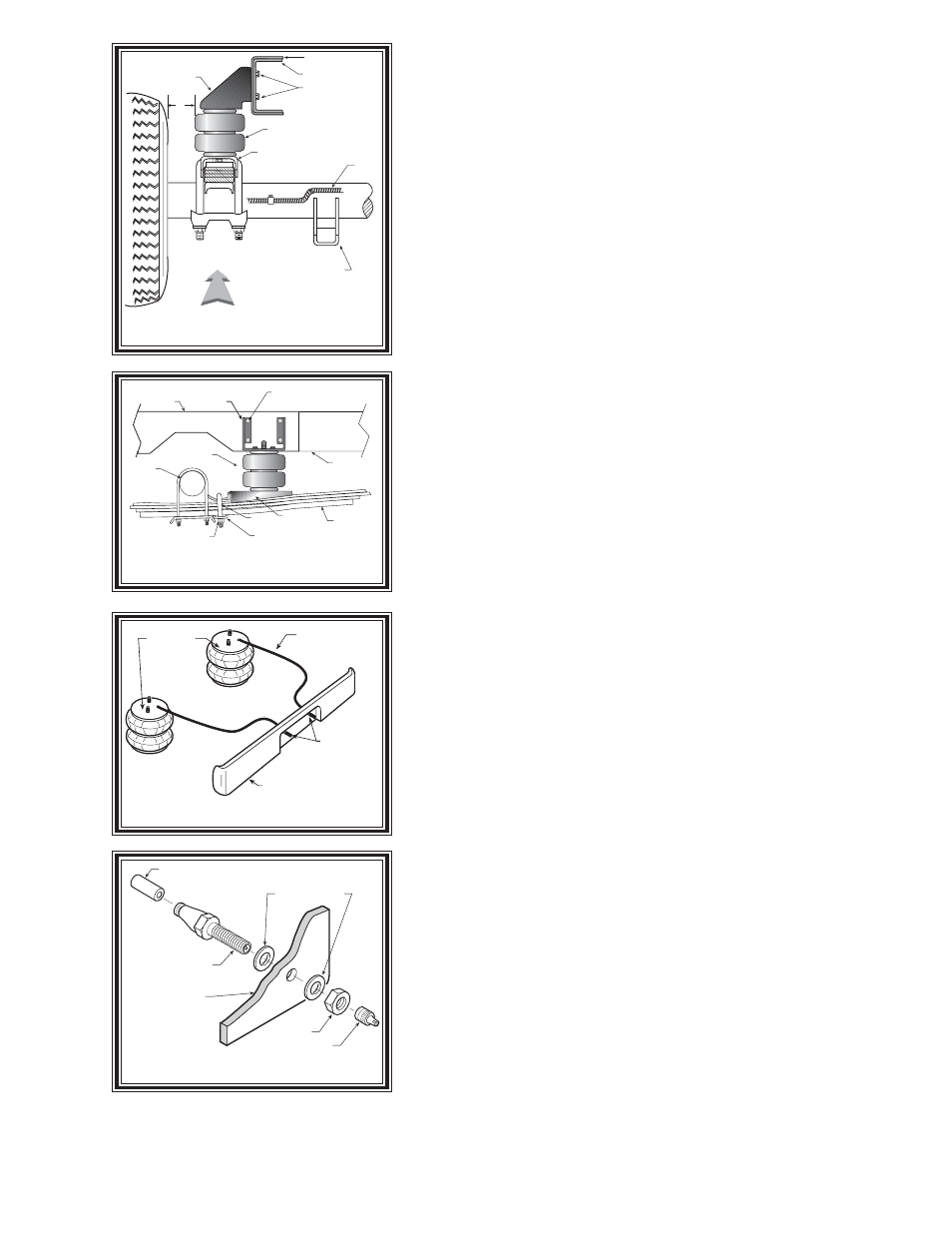
Figure "E"
Figure "B"
Figure "D"
N
OTE
:
Please read thorough this manual completely before installing the air spring
kit to your vehicle.
S
TEP
1 - P
REPARE
THE
VEHICLE
With the vehicle on a solid, level surface chock the front wheels. Remove
the negative battery cable. Raise the vehicle by the axle and remove the rear
wheels. After the removal of the wheels lower the vehicle so the axle rests on
jack stands rated for your vehicles weight.
S
TEP
2 - P
RE
-
ASSEMBLE
THE
KIT
Select one air helper spring from your kit. Install the upper bracket by
inserting the air helper spring studs into the holes, use two 3/8" - 16 lock nuts
to secure the bracket to the air spring, see Figure "A". Install the air fitting as
shown in Figure "A". Tighten the air fitting securely to engage the orange thread
sealant. Position the elbow so as to point in the anticipated location of the air
inflation valve see Figures "A" & "C". Fasten the lower bracket to the air helper
spring using a 3/8"-16 x 3/4" flange lock bolt, see Figure "A".
S
TEP
3 - I
NSTALLING
THE
ASSEMBLY
TO
THE
VEHICLE
With "C" Channel Support
When installing this kit on a truck with a "C" channel support in place, the
upper bracket will bolt in the existing "C" channel support holes, refer to Figure
"A". Remove the four mounting bolts on the rearward side of the axle. Install the
upper bracket with 1/2"-13 X 1-3/4" hex bolts. Fasten the upper bracket to the
backside of the frame rail using 1/2"-13 lock nuts and washers. Attach the lower
bracket to the leaf stack using the bail clamp, bracket strap, and 3/8"-16 lock
nuts. The bracket strap is used to clamp the lower bracket to the leaf stack, refer
to Figure "A" & "C".
Without "C" Channel Support
Place the assembly on the top of the passenger's side leaf spring stack
rearward of the axle, see Figures “A”, "B" & “C”. Attach the lower bracket to
the leaf stack using the bail clamp, bracket strap, and 3/8"-13 lock nuts. The
bracket strap is used to clamp the lower bracket to the leaf stack, refer to Figure
"A". Before marking and drilling the holes for the upper bracket, make sure the
mounted height of the air spring is between 5.00" and 6.00", and the upper and
lower brackets are parallel as possible. Mark the four holes to be drilled with
a center punch using the upper bracket as a template. Before drilling, ensure
that there are no electrical, fuel, or brake lines on the opposite side of the
mounting surface that can be damaged by the drill. Inserting a piece of wood
between the frame rail and any lines in the path of the drill can help avoid damage
to these lines. Drill four holes in the frame rail using a 1/2" drill bit. Install the
1/2"-13 X 1-3/4" hex bolts through the upper bracket holes and the holes that
were drilled in the frame rail. Fasten the upper bracket to the backside of the
frame rail using 1/2"-13 lock nuts and washers.
S
TEP
4 - I
NSTALL
THE
AIR
LINE
AND
INFLATION
VALVE
Uncoil the airline tubing and cut it into two equal lengths. DO NOT FOLD
OR KINK THE AIRLINE TUBING. Try to make the cut as square as possible.
Insert one end of the airline tubing into the air fitting installed in the top of the
air helper spring. Push the airline tubing into the fitting as far as possible.
Figure "C"
DRIVER'S SIDE
FROM REAR, LOOKING TO FRONT
UPPER
BRACKET
SHOCK
BRACKET
LOWER BRACKET
AIR SPRING
FRAME RAIL
BRAKE
LINE
C-CHANNEL
1/2” LOCK NUT
1/2”
MIN
UPPER
BRACKET
FRAME RAIL
UPPER
BRACKET
AXLE
1/2”-13 X 1 3/4”
HEX BOLTS
LOWER
BRACKET
AIR
SPRING
LEAF SPRINGS
BAIL
CLAMP
BRACKET
STRAP
3/8”-16
LOCK NUT
“C”
CHANNEL
AIR HOSE
INFLATION
VALVES
BUMPER
AIR
SPRINGS
AIR LINE
PUSH-TO-CONNECT
INFLATION VALVE
FLAT WASHER
HEX NUT
VALVE CAP
BODY OF
VEHICLE