1 - p, 2 - p, 3 - p – Rite-Ride 2065 User Manual
Page 3: 4 - i, 5 - i
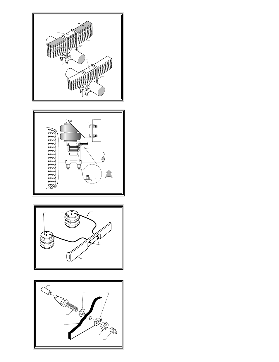
OVERLOAD SPRINGS
(TO BE REMOVED)
U BOLTS
U BOLT NUTS
U BOLT NUTS
SPACER
RETAINER
PLATE
NEW
U BOLTS
NEW
U BOLT NUTS
RETAINER
PLATE
BEFORE
AFTER
DRIVER'S SIDE
FRONT
BAIL CLAMP
.50
.50
P
LEASE
READ
FIRST
This kit installation requires the removal of the overload leaf spring.
It is recommended that once the overload spring is removed that new leaf
spring "U" bolts and nuts be used to reassemble the primary leaf springs.
Your local spring shop should be contacted for new "U" bolts and nuts
see Figure "B".
S
TEP
1 - P
REPARE
THE
VEHICLE
With the vehicle on a solid, level surface chock the front wheels.
Raise the vehicle by the rear axle and remove the rear wheels. After the
removal of the wheels lower the vehicle so the axle rests on jack stands
rated for your vehicles weight. Make sure the positive battery cable is
disconnected from the battery. For proper installation of this kit the
overload spring and spacer must be removed from the leaf spring stack.
Remove the leaf spring "U" bolts by carefully removing the nuts from the
leaf spring "U" bolts see Figure "B". Remove the overload springs and
spacer. Reassemble the retainer plate and apply new "U" bolts and nuts
supplied by your local spring shop.
Torque the "U" bolts to the manufacturers specifications.
S
TEP
2 - P
REASSEMBLE
THE
RIDE
-
RITE
KIT
Select one air helper spring from your kit and an upper bracket. Align
the studs on the air spring with the holes on the upper bracket making sure
the air inlet hole can be seen through the large hole in the upper bracket
see Figure "A". Use the 3/8"-16 flange lock nuts to secure the upper
bracket to the air spring. Install the air fitting as shown in Figure "A".
Tighten the air fitting securely to engage the orange thread sealant. Point
the elbow fitting in the direction of the inflation valve location. Position
the lower bracket as shown in Figure "A" & "C" fasten the lower bracket
to the air helper spring using two 3/8"-16 x 3/4" hex bolts.
S
TEP
3 - P
RE
-
FIT
MARK
AND
DRILL
HOLES
Set the air spring assembly onto the leaf stack and visually align the
air spring. The upper bracket flange will work as a template for marking
the holes to be drilled. Make sure there is 5.00" to 6.50" between the
upper and lower bracket. Before drilling the holes make sure all
electrical, brake and fuel lines are cleared from the path of the drill.
Damage to lines can be avoided by inserting a piece of wood between the
frame rail and any lines in the path of the drill. Drill the four holes in the
frame rail using a 7/16" drill bit see Figure "A".
S
TEP
4 - I
NSTALLATION
TO
THE
VEHICLE
After drilling the holes in the frame rail install the 3/8"-16 x 1 1/2" hex
bolts through the upper bracket holes and the holes that were drilled in
the frame rail. Next fasten the upper bracket to the frame rail using the
3/8"-16 flange lock nuts and special flat washers to the back side of the
frame rail refer to Figure "A" & "C". The next step is to attach the lower
bracket to the leaf spring assembly. Insert (2) of the bail clamps through
the holes in the lower bracket as shown in Figure "A". The bail clamp
should straddle the leaf stack refer to Figure "A" & "C". Fasten using the
3/8"-16 flange lock nuts. Some applications may require that the bail
clamp be trimed. The height of the bail clamp above the fastening nut
is not to exceed .50" see Figure "C".
S
TEP
5 - I
NSTALLATION
TO
THE
PASSENGER
'
S
SIDE
ASSEMBLY
Follow steps 1-4 for assembly and installation of the passenger's side
assembly.
Figure "B"
Figure "E"
AIR LINE
PUSH-TO-CONNECT
INFLATION VALVE
FLAT WASHER
HEX NUT
VALVE CAP
BODY OF
VEHICLE
Figure "D"
AIR HOSE
INFLATION
VALVES
BUMPER
AIR
SPRINGS
Figure "C"