1 - p, 2 - p, 3 - i – Rite-Ride 2430 User Manual
Page 3: 4 - i, 5 - i
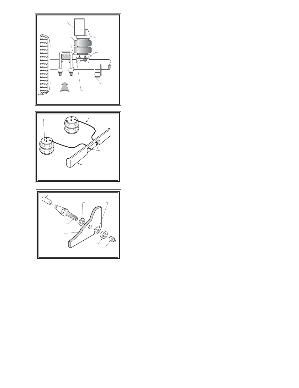
UPPER
BRACKET
FRAME RAIL
AIR SPRING
SHOCK
BRACKET
J-BOLT
LOWER
BRACKET
DRIVER'S SIDE
FRONT
JOUNCE PAD
F
IGURE
"D"
F
IGURE
"C"
S
TEP
1 - P
REPARE
THE
VEHICLE
/ U
PPER
BRACKET
INSTALLATION
This installation assumes that there is no load in the bed of the truck. It is not
necessary to remove the wheels for installation of this kit.
Your vehicle is equipped with rubber jounce bumpers. The bumpers are
attached to the frame directly above the axle. Remove these bumpers by unbolting
from the frame. This bumper will not be reused with this kit.
Attach the upper bracket to the frame where the jounce bumper was removed
using the 10MM X 50MM flat head bolt, placing the spacer between the upper
bracket and the frame, as shown in Figure "A".
S
TEP
2 - P
RE
-
ASSEMBLE
THE
KIT
Pre-assembly will begin with the left (driver's) side of the vehicle. All pictures
depict the installation on the left side of the vehicle unless noted otherwise. Attach
the lower bracket to the air spring using a 3/4" flange hex bolt. Be sure that the lower
bracket is attached to the air spring so that the bracket orientation is perpendicular
to the leaf stack. See Figures "A" & "B".
S
TEP
3 - I
NSTALL
THE
ASSEMBLY
TO
THE
VEHICLE
Place the air spring assembly on top of the jounce bumper pad on the axle
housing, with the narrow end inserted inbetween the axle u-bolts. Insert the large
stud on the air spring into the large hole in the upper bracket. See Figures "A" &
"B". The alignment pin on the air spring will be inserted into one of the small holes
in the upper bracket. Use which ever hole provides the best alignment. Secure the
air spring to the upper bracket using the 5/8" jam nut. Install the air fitting into the
large stud on the air spring and tighten it enough to engage the orange thread
sealant, see Figure "A". On the drivers side only, the parking brake line will need
to be tie-wrapped to the upper bracket, see Figure “A”.
With the assembly attached to the frame rail, the next step is to attach the lower
bracket to the jounce pad on the axle housing. Center the lower bracket on the
jounce pad. Use the J-bolts and 5/16" -18 flanged lock nuts to secure the lower
bracket to the jounce pad see Figures "A" & "B". Spin the nuts on as far as
possible by hand. While making sure that the lower bracket stays centered on the
jounce pad, tighten each nut two turns at a time with a wrench, switching to
opposite nuts to ensure that the bracket is mounted evenly on the jounce pad.
Important: In order for the air spring to function properly, there must be a
minimum of 1/2" of clearance around the air spring.
S
TEP
4 - I
NSTALL
THE
PASSENGER
'
S
SIDE
ASSEMBLY
Follow steps 2 - 5 for assembly and installation of the passenger's side assembly.
S
TEP
5 - I
NSTALL
THE
AIR
LINE
AND
INFLATION
VALVE
Uncoil the air tubing and cut it in two equal lengths. DO NOT FOLD OR KINK THE TUBING. Make the cut as square as possible.
Insert one end of the tubing into the push-to-connect male fitting installed in the top of the air helper spring as far as possible.
Select a location on the vehicle for the air inflation valves. The location can be on the bumper or the body of the vehicle, as
long as it is in a protected location so the valve will not be damaged, but still maintain accessibility for the air chuck see Figure
"C". Drill a 5/16" hole and install the air inflation valve using two 5/16" flat washers per valve as supports see Figure "D". Run
the tubing from the air helper spring to the valve, routing it to avoid direct heat from the engine, exhaust pipe, and away from sharp
edges. Thermal sleeves have been provided for these conditions. The air line tubing should not be bent or curved sharply as it
may buckle. Secure the tubing in place with the nylon ties provided. Push the end of the air line tubing into the inflation valve see
Figure "D".
F
IGURE
"B"
AIR HOSE
INFLATION
VALVES
BUMPER
AIR
SPRINGS
AIR LINE
PUSH-TO-CONNECT
INFLATION VALVE
FLAT WASHER
HEX NUT
VALVE CAP
BODY OF
VEHICLE