1 - p, 2 - p, 3 - i – Rite-Ride 2209 User Manual
Page 3: 4 - i
F
IGURE
"D"
F
IGURE
"C"
S
TEP
1 - P
REPARE
THE
VEHICLE
Remove the negative battery cable. With the vehicle on a solid, level surface
chock the front wheels. Raise the vehicle by the axle and remove the rear wheels.
After the removal of the wheels lower the vehicle so the axle rests on jack stands
rated to support your vehicle's weight.
S
TEP
2 - P
REASSEMBLE
THE
KIT
Pre-assembly will begin with the right (passenger's) side of the vehicle. All
pictures show the installation on the right side of the vehicle unless noted
otherwise. Select an air spring and the right-hand upper bracket from your kit see
Figure "A". Align the holes in the top of the air spring with the mounting holes
in the upper bracket, making sure the air inlet hole is visible through the slot in the
bracket. Secure the bracket to the air spring using two 3/8" -16 x 3/4"flanged hex
bolts see Figure "A". Next, install the air fitting through the slot in the upper bracket
and into the air spring. Tighten the air fitting so as to make contact with the nylon
ring and then tighten 1/4 turn to snug the fitting. No thread sealant is required on
the air fitting. Select a lower bracket from your kit. Insert two 3/8" -16 x 3" carriage
bolts through the square holes in the lower bracket. Align the mounting hole in
the lower bracket as shown in Figure "A" with the hole in the bottom of the air
spring. Install the disk between the bottom of the air spring and the lower bracket.
Fasten the lower bracket to the air spring using a 3/8" -16 x 3/4" flanged hex bolt
(finger tight).
S
TEP
3 - I
NSTALL
THE
ASSEMBLY
TO
THE
VEHICLE
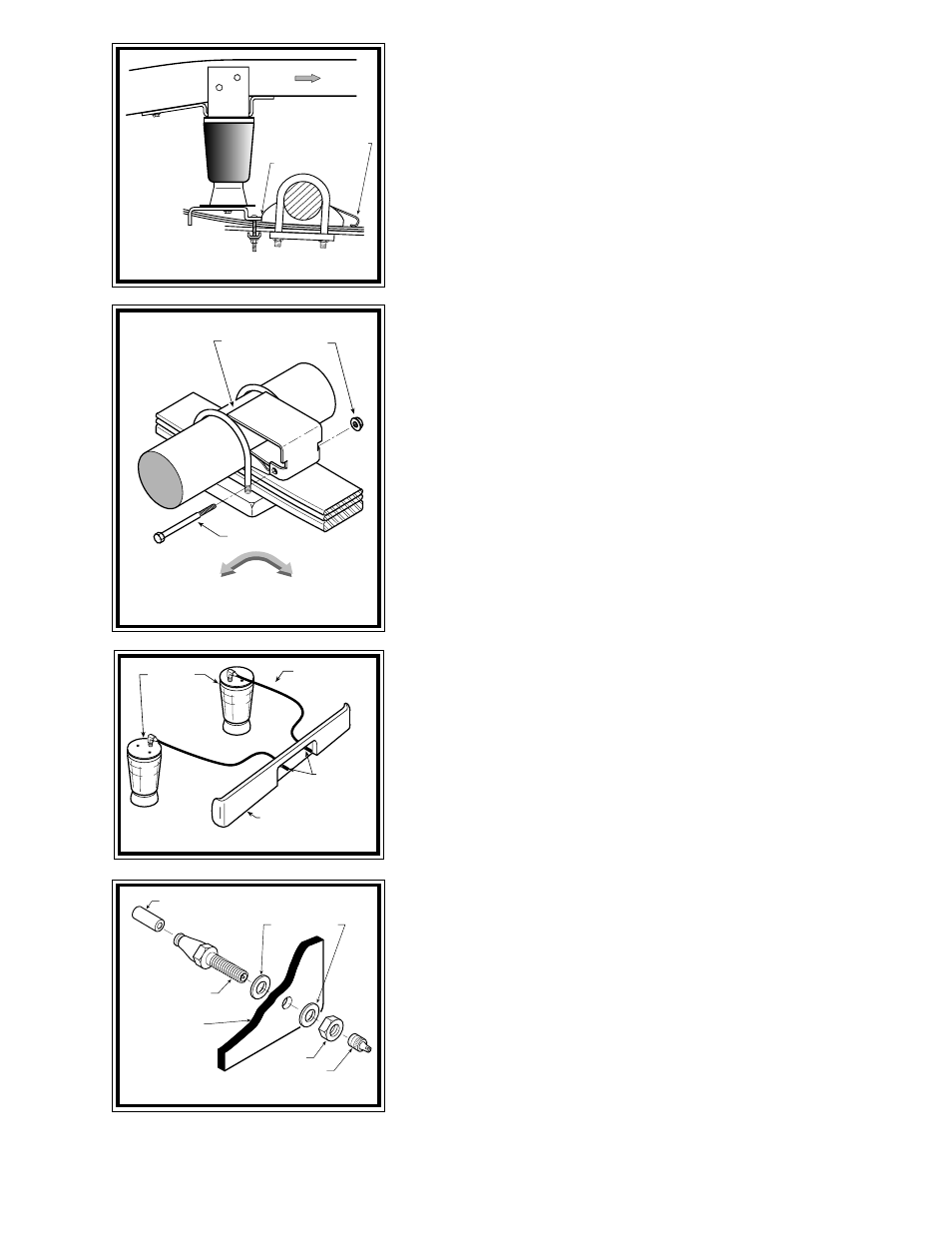
Position the air spring assembly on top of the leaf spring just behind the axle.
The lower bracket must be butted against the axle cradle see Figure "B". It may
be necessary to compress the air spring assembly to properly position the upper
bracket. On some models, there is a hole in the bottom of the frame flange that will
line up with the hole in the tab on the upper bracket. Insert a 3/8" -16 x 1-1/2" hex
bolt through the hole in the slanted tab of the upper bracket and the hole in the
bottom of the frame rail (if applicable). Install a 3/8" washer and 3/8" -16 flanged
hex nut on the bolt see Figures "A" & "B". If this hole is not available on your
vehicle, orient the upper bracket so that the air spring is as close to vertical as
possible. The upper bracket should be seated against the bottom of the frame rail.
Using the holes in the vertical tab of the upper bracket as a template, drill two
13/32" holes through the side of the frame rail. Hint: Once the locations of the holes
has been marked, drilling can be made easier by first drilling a 1/8" diamater hole
then finishing with a 13/32" drill bit. Attach the upper bracket to the frame rail
by inserting two 3/8" -16 x 1-1/2" hex bolts through the upper bracket and frame rail
and secure them with two 3/8" -16 hex nuts and 3/8" flat washes see Figure "A".
When drilling through the frame, make sure that all brake, electrical, and fuel lines
will clear the path of the drill on the inside the frame rail. A block of wood placed
between the inside of the frame and and the lines can help to avoid damaging these
lines while drilling. Slide the bracket strap over the carriage bolts and against the
bottom of the leaf spring. Secure the bracket strap to the lower bracket with two
3/8" -16 flanged hex nuts. Tighten the 3/8" -16 hex bolt securing the air spring to
the lower bracket.
Your air helper spring kit includes a jounce spacer bracket. Install this bracket
on the leaf spring, just forward of the axle see Figures "A" & "B". Insert a 5/16"
-18 x 3-1/2" hex bolt through the holes in the jounce spacer, underneath the factory
jounce pad, and secure with a 5/16" -18 hex nut.
S
TEP
4 - I
NSTALL
THE
DRIVER
'
S
SIDE
ASSEMBLY
Follow steps 2 and 3 for the installation of the driver's side assembly. Reverse
any orientations when assembling and installing the air spring on the driver's side
of the vehicle.
F
IGURE
"B"
WHEEL
FRONT
5/16” -18 x 3-1/2”
HEX BOLT
5/16” -18
FLANGED
HEX NUT
JOUNCE
SPACER
AIR HOSE
INFLATION
VALVES
BUMPER
AIR
SPRINGS
FRONT
BUTT LOWER BRACKET
AGAINST AXLE CRADLE
PASSENGER’S SIDE
FACTORY
JOUNCE PAD
F
IGURE
"E"
AIR LINE
PUSH-TO-CONNECT
INFLATION VALVE
FLAT WASHER
HEX NUT
VALVE CAP
BODY OF
VEHICLE