Rite-Ride 2100 User Manual
Page 3
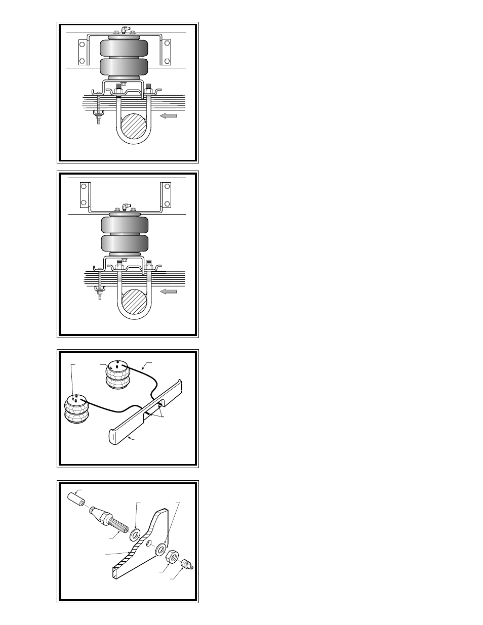
FRONT
FRONT
FIGURE B
FIGURE "C"
FIGURE "D"
FIGURE "E"
S
TEP
1 - P
REPARE
THE
VEHICLE
With the vehicle on a solid, level surface chock the front wheels. Raise
the vehicle by the axle and remove the rear wheels. After the removal of
the wheels lower the vehicle so the axle rests on jack stands rated for your
vehicles weight.
S
TEP
2 - I
NSTALL
THE
AIR
FITTING
Install the brass elbow fitting into the air spring through the large
access hole in the upper bracket. Tighten the air fitting securely to engage
the orange thread sealant. Position the elbow so as to point in the
anticipated location of the air inflation valve see Figure "A" & "D".
S
TEP
3 - A
SSEMBLE
THE
UPPER
BRACKET
TO
THE
AIR
SPRING
This kit is designed to fit two and four-wheel-drive Suburbans. Please
follow Step “3A” for two-wheel-drive vehicles and Step “3B” for four-
wheel-drive vehicles.
S
TEP
3
A
- T
WO
WHEEL
DRIVE
MOUNTING
Using the air spring prepared in Step 2 and an upper bracket, position the
upper bracket as shown in Figure "A" & "B". Insert the air fitting through the
large hole in the bracket and align the studs as shown in Figure "A" & "B".
Secure using 3/8"-16 flanged lock nuts. Proceed to Step 4.
S
TEP
3
B
- F
OUR
WHEEL
DRIVE
MOUNTING
Using the air spring prepared in Step 2 and an upper bracket, invert the
upper bracket as shown in Figure "A" & "C". Insert the air fitting through
the large hole and align the studs as shown in Figure "A" & "C". Secure
using 3/8"-16 flanged lock nuts. The balance of the kit installation is the
same as the two-wheel-drive installation.
S
TEP
4 - M
OUNTING
LOWER
BRACKET
Select a lower bracket from your kit. Position the lower bracket and
upper bracket as shown in Figure “A”. Secure the lower bracket to the air
spring using a 3/8"-16 x 3/4" flanged lock bolt through the hole in the
lower bracket that will be closest to the wheel see Figures "A". Proper hole
selection for mounting the air spring to the lower bracket will provide
proper air spring alignment.
S
TEP
5 - P
RE
-
FIT
/
MARK
AND
DRILL
HOLES
Position the assembly on the leaf spring and retainer as shown in
Figure "A" & “B". The lower bracket will sit on the leaf spring retainer as
shown in Figure "B". The lower bracket has been notched so that it will
fit over the edges of the retainer. The opposite end of the lower bracket
will fit forward of the retainer and will rest on top of the leaf spring stack
see Figure "A" & "B".
Next, position the upper bracket against the frame so that the lower
right-hand-mounting hole aligns with an existing 5/16" diameter hole in
the frame rail. This hole must be enlarged to 7/16" diameter. Before
drilling it is recommended that the positive battery cable be discon-
nected. Before drilling the holes make sure all electrical, brake and fuel
lines are cleared from the path of the drill. Damage to lines can be avoided
by inserting a piece of wood between the frame rail and any lines in the path
of the drill. Use a 7/16" diameter drill bit and enlarge the 5/16" hole.
AIR HOSE
INFLATION
VALVES
BUMPER
AIR
SPRINGS
AIR HOSE
PUSH-TO-CONNECT
INFLATION VALVE
FLAT WASHER
HEX NUT
VALVE CAP
BODY OF
VEHICLE
2WD
4WD