Step 1 - prepare the vehicle, Step 2 - pre-assemble the kit, Step 3 - installing the assembly to the vehicle – Rite-Ride 2361 User Manual
Page 3: Step 5 - install the air line and inflation valve, Figure "d, Figure "b, Figure "c, Figure "e
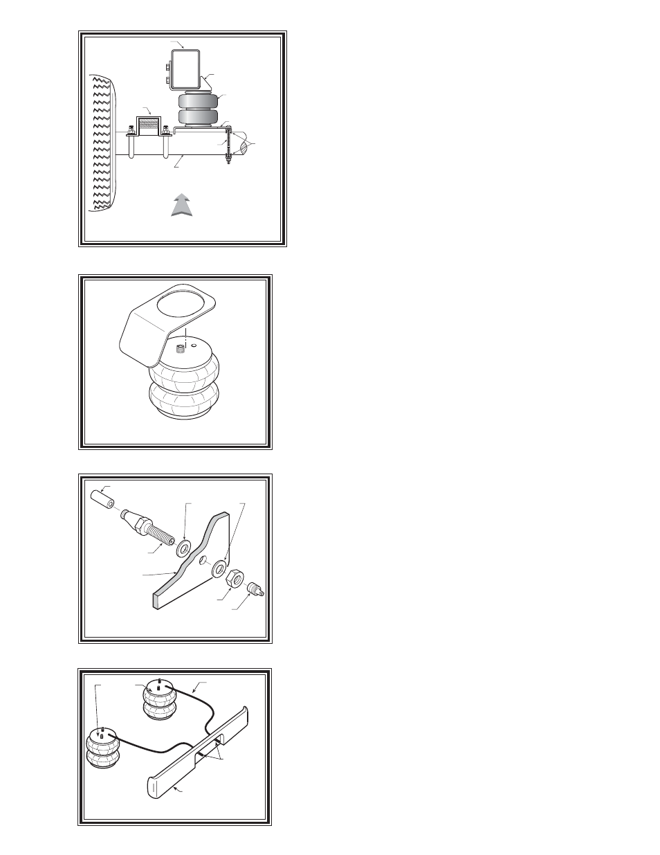
Figure "D"
NOTE:
Please read thorough this manual completely before installing
the air spring kit to your vehicle. All illustrations reference the
driver’s or left side of the vehicle. Reverse all orientations for the
passenger’s or right side.
STEP 1 - PREPARE THE VEHICLE
Remove the jounce bumper located on the axle. The jounce
bumpers will not be reused with this kit.
STEP 2 - PRE-ASSEMBLE THE KIT
Select one air helper spring from your kit. Attach the left lower
bracket to the air spring using the 3/8"-16 x 5/8 flat head bolt.
The narrow end of the bracket will face the leaf stack. See
Figure "A". Note: This kit has a specific left and right
lower bracket.
STEP 3 - INSTALLING THE ASSEMBLY TO THE VEHICLE
Select an upper bracket and place it on the frame. Note: the
upper bracket will have a snug fit and may require tapping
with a hammer. Pre drill three 5/16" holes in the frame. Using three
of the 3/8"-16 X 1" self tapping bolts, install the upper bracket onto
the frame. See Figure "A". Note: The rearward edge of the
upper bracket must be 0.75" forward of the reinforcement
seam on the frame. See Figure "A". Place the assembly on the
axle on the driver’s side. Place one of the bracket clamps between
the lower bracket and the axle. See Figures "A" & "B". Attach
the lower bracket and bracket clamp to the axle using a second
bracket clamp, two 3/8"-16 x 5 1/2" carriage bolts, and 3/8"-16
flange lock nuts. See Figures "A" & "B". Next, use one of the 3/
8"-16 X 2 1/2" hex bolts and a 3/8"-16 flange lock nut and attach
the forward flange of the lower bracket to the axle using the hole
from the jounce bumper removeal. See Figure “A”. The lower
bracket will fit without altering the brake lines. Once the assembly is
in place, you must have a minimum of 1/2" clearance around the air
spring. Attach the upper bracket to the air spring with a 5/8"-18
nylon jam nut. The alignment "button" will use the smaller diameter
hole. Install the elbow fitting into the air spring. Tighten the air fitting
securely to engage the orange thread sealant. Position the fitting to
point to the anticipated location of the air inflation valves, see Figure
"A" & "E".
STEP 4 - INSTALLATION OF THE PASSENGER’S SIDE
ASSEMBLY
Follow steps 1-3 with reverse orientations for assembly and installa-
tion of the passenger’s side. This side will use a heat installed
between the upper bracket and the air spring. See Figure "C"
.
STEP 5 - INSTALL THE AIR LINE AND INFLATION VALVE
Uncoil the airline tubing and cut it into two equal lengths. DO NOT
FOLD OR KINK THE AIRLINE TUBING. Try to make the cut as
square as possible. Insert one end of the airline tubing into the air
fitting installed in the top of the air helper spring.
UPPER
BRACKET
LOWER BRACKET
AIR SPRING
FRAME
AXLE
DRIVER'S SIDE
FROM REAR, LOOKING TO FRONT
BRACKET
CLAMP
3/8-16 X 5 1/2
CARRIAGE
BOLT
LEAF
STACK
Figure "B"
HEAT SHIELD
Figure "C"
AIR LINE
PUSH-TO-CONNECT
INFLATION VALVE
FLAT WASHER
HEX NUT
VALVE CAP
BODY OF
VEHICLE
Figure "E"
AIR HOSE
INFLATION
VALVES
BUMPER
AIR
SPRINGS