Step 2—pre-assemble the kit, Step 3—install the assembly to the vehicle – Rite-Ride 0830 User Manual
Page 3
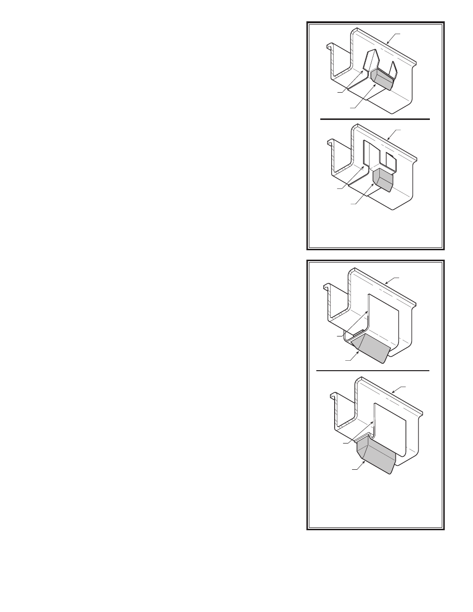
Figure “B”
VEHICLE
FRAME
JOUNCE
BUMPER
JOUNCE
BUMPER
BRACKET
Your vehicle may be equipped with a jounce bumper
located on the frame above the axle. Remove the
jounce bumper by sliding/prying it out of the slot in
the bracket.
Any portion of the bracket that extends
below the bottom of the frame rail must be
removed. Care should be taken not to weaken the
frame if a torch is used.
VEHICLE
FRAME
JOUNCE
BUMPER
JOUNCE
BUMPER
BRACKET
VEHICLE
FRAME
JOUNCE
BUMPER
JOUNCE
BUMPER
BRACKET
Your vehicle may be equipped with a jounce bumper
located on a mounting bracket inside the frame above
the axle. Remove the jounce bumper from the bracket
by sliding it out of the slotted hole on the bracket.
VEHICLE
FRAME
JOUNCE
BUMPER
JOUNCE
BUMPER
BRACKET
Figure “C”
STEP 2—PRE-ASSEMBLE THE KIT
Install the push-to-connect elbow fitting in the top of the air spring.
Tighten the fitting securely to engage the orange thread sealant. Posi-
tion the fitting so that it points toward the inside of the vehicle
see
Figures “A” & “E”. The elbow should be installed so that it does not
point toward the exhaust pipe. Align the threaded studs on the air
spring with the slots in the upper bracket. Insert the threaded studs
into the slots in the bracket and install the brace that corresponds to
your vehicle
see Figure “A”. If your vehicle requires either 90 degree
or angled adapter, install 3/8" -16 x 3/4" flanged hex bolt in the brace
before attaching it to the upper bracket
see Figure “A”. Secure the
upper bracket and adapter to the air spring with two 3/8" -16 hex nuts
(finger tight).
Select a lower bracket from your kit. Install four 3/8" -24 x 2-1/2"
ribbed neck bolts in the four holes in the lower bracket and seat them
in the bracket with a hammer
see Figure “A”. Attach the lower bracket
to the air spring with two 3/8" -16 x 3/4" flanged hex bolts. Either set
of holes in the lower bracket may be used to attach the bracket to
the air spring. Use the set of holes that allows the assembly to set on
the axle housing without interfering with the vehicle’s shock bracket.
STEP 3—INSTALL THE ASSEMBLY TO THE VEHICLE
Set the air spring assembly on top of the axle housing so that the lower
bracket straddles the vehicle’s shock bracket
see Figure “D”. Position
the assembly so that the upper bracket is flush against the side of the
frame rail. If your vehicle requires the upper bracket brace, the brace
should be flush against the inside of the frame rail. Ensure that the air
spring is aligned vertically
see Figures “A” & “D”.
Using the holes in the upper bracket as a template, drill two 3/8”
holes completely through the frame rail.
Before drilling the holes,
make sure all electrical, brake, and fuel lines are cleared from the
path of the drill. In order to prevent any damage to these lines, it is
recommended that a thin piece of wood be placed between the frame
rail and the existing lines while drilling the frame. Secure the assembly
to the frame using the provided 1/4" -20 x 4-1/2" hex bolts, 1/4" flat
washers, 1/4" lock washers, 1/4" -20 hex nuts, and steel sleeves
see
Figure “A”. Do not over-tighten.
NOTE: If your vehicle requires the upper bracket brace, the hex bolts
will pass through the upper bracket, frame rail, and brace. If your
vehicle requires either 90 degree or angled adapter, the hex bolts will
only pass through the upper bracket and frame rail
see Figure “A”.
On vehicles requiring the upper bracket brace, secure the brace to
the jounce bumper bracket with the provided 3/8" -16 flanged lock
nut, 3/8" flat washer, and the installed flanged hex bolt.
NOTE: On some vehicles, the 3-1/2" sleeve will not span the entire
gap in the frame rail. In such cases, it may be necessary to use the
3/8" and 3-1/2" sleeves together to span the gap in the frame rail.
Do not use the sleeves if they prevent the bolt from being tightened
securely on the frame. The sleeves are used to prevent the bolts from
being over-tightened and crushing the vehicle’s frame.
NOTE: The holes in the axle straps are not centered on the strap.
The orientation of the axle straps can be changed so that they clear
the vehicle’s shock bracket on the axle housing.
Secure the lower bracket to the axle housing by installing two axle
straps underneath the axle. Secure the axle straps to the ribbed neck
bolts with the 3/8" -24 nylon insert lock nuts. Tighten the 3/8" -16 hex
nuts, securing the air spring and brace to the upper bracket.
Re-install the wheel and torque the lug nuts to factory specifica-
tions. Raise the vehicle by the frame and remove the jack stands.
STEP 4 —INSTALL THE AIR LINE AND THE
INFLATION VALVE
Uncoil the air line tubing and cut it into two equal lengths.
DO NOT
FOLD OR KINK THE TUBING. Try to make the cut as square as pos-
sible. Insert one end of the tubing into the air fitting installed in the
top of the air spring. Push the tubing into the fitting as far as possible.