Rite-Ride 2517 User Manual
Page 3
S
TEP
1 - P
REPARE
THE
VEHICLE
With the vehicle on a solid level surface, chock the front wheels.
Raise the rear of the vehicle by the axle and remove the rear wheels.
After the removal of the wheels, lower the vehicle so the axle rests on
jack stands rated for your vehicle's weight. Remove the negative
battery cable.
S
TEP
2 - P
RE
-
ASSEMBLE
THE
KIT
Pre-assembly will begin with the right, or passenger's side of the
vehicle. Select one air helper spring, an upper bracket, and an upper
bracket support from your kit. Attach the air spring to the upper bracket
and support bracket using two 3/8"-16 x 1" flange head bolts, see Figure
"A". Next, install the male fitting into the air spring. Tighten the fitting
until the nylon o-ring makes contact with the air spring, then tighten it one
an additional turn.
Select one lower bracket and one disk from your kit. Insert two of
the 3/8"-16 x 3-1/2" carriage bolts into the square holes in the lower
bracket. Attach the bracket and disk to the air spring using one of the
3/8"-16 x 3/4" flat head bolts finger tight, see Figure "A". NOTE: the
outside hole in the lower bracket will be used to secure the air spring
to the lower bracket.
S
TEP
3 - A
TTACH
THE
ASSEMBLY
TO
THE
LEAF
SPRING
Place the assembly on top of the leaf spring stack, forward of the
axle see Figures "A" & "B". The hook on the lower bracket should
capture the leaf spring U-bolt as shown in Figure "B". Attach the
lower bracket to the leaf stack by installing a bracket clamp on to the
carriage bolts, and securing it two 3/8" -16 flanged hex nuts. See Figure
"A".
S
TEP
4 - M
ARK
AND
DRILL
THE
HOLES
IN
THE
FRAME
RAIL
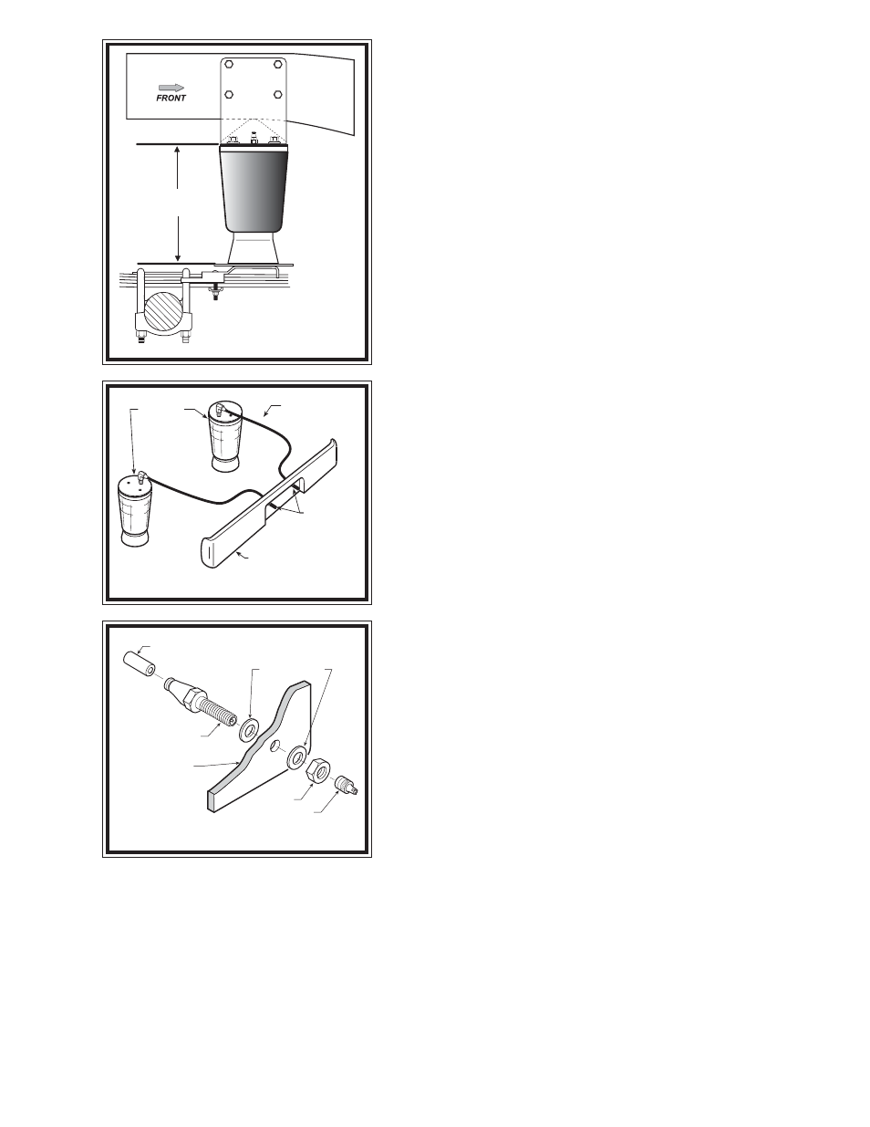
Align the air spring so that it is as close to vertical as possible and the
upper and lower brackets are parallel. The distance between the
brackets should be between 6-1/4" and 6-1/2". Position the upper
bracket so that it is flush against the outside of the frame rail. The small
tab on the bracket should rest against the bottom of the frame rail. See
Figures "A" & "B".
Using the holes in the upper bracket as a template drill four 7/16"
holes in the frame rail, making sure that any brake, fuel, or electrical lines
inside the frame rail will not be damaged by the drill. See Figures "A"
& "B".
S
TEP
5 - A
TTACH
THE
UPPER
BRACKET
Once the holes have been drilled in the frame rail, attach the upper bracket to the frame using the supplied 3/8" -
16 x 1-1/2" hex bolts, large flat washers, and the 3/8" -16 flanged hex nuts as shown in Figure "A". Tighten the 3/
8" flat head bolt securing the air spring to the lower bracket.
S
TEP
6 - I
NSTALL
THE
DRIVER
'
S
SIDE
ASSEMBLY
Follow steps 1-5 for assembly and installation on the driver's side.
Figure "B"
Figure "D"
Figure "C"
AIR HOSE
INFLATION
VALVES
BUMPER
AIR
SPRINGS
AIR LINE
PUSH-TO-CONNECT
INFLATION VALVE
FLAT WASHER
HEX NUT
VALVE CAP
BODY OF
VEHICLE
FRAME
PASSENGER’S SIDE
6.25”-6.5”