Step 8 — install the inflation valve, Step 9 — inflate and test – Rite-Ride 4168 User Manual
Page 2
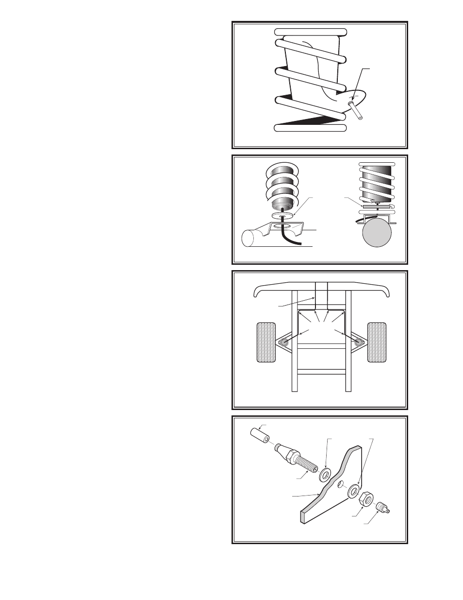
STEP 8 — INSTALL THE INFLATION VALVE
Drill a 5/16" hole and install the air inflation valve using
two 5/16" flat washers as supports, see Figure “D”. Run
the tubing from the air helper spring to the inflation valve,
routing it to avoid direct heat from the exhaust pipe and
away from sharp edges.
Cut the excess air line tubing so that it will fit eas-
ily into the inflation valve, making sure the end is cut
squarely (a "saw" cut with a sharp knife is preferred). The
air line tubing should not be bent or curved sharply, as
it may buckle. Secure the tubing in place with the nylon
ties provided. Push the end of the air line tubing into the
inflation valve, see Figure “D”.
FOLLOW STEPS 2-8 FOR THE OTHER AIR SPRING.
STEP 9 — INFLATE AND TEST
Inflate the air springs to recommended maximum operat-
ing pressure (see page 1 for operating pressures). With
an applied solution of soap and water, check for air leaks
around the fittings and valve core. Replace the wheels and
torque the lug nuts to the manufacturer's specification.
Jack the vehicle up, remove the jack stands, and lower
the vehicle to the ground. Remove the wheel chocks from
the front wheels. Reattach the negative battery cable. We
recommend inflating and deflating in 5 p.s.i. increments
to find the ideal riding condition for your vehicle.
PLEASE TAKE ALL NECESSARY
SAFETY PRECAUTIONS WHEN INSTALLING
YOUR COIL-RITE KIT.
FIGURE “A”
FIGURE “B”
FIGURE “C”
AIR
INLET
AIR SPRING
SUPPORT
NYLON
TIES
AIR LINE
PUSH-TO-CONNECT
INFLATION VALVE
BODY OF
VEHICLE
AIR LINE
FLAT WASHER
HEX NUT
VALVE CAP
FIGURE “D”