Air line installation – Rite-Ride 4188 User Manual
Page 2
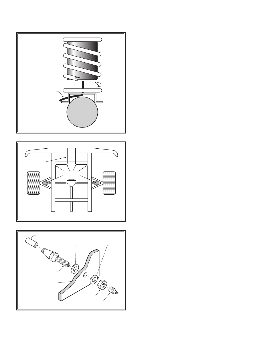
AIR LINE INSTALLATION
Figure “C”
Please take all necessary safety precautions
when installing your Coil-Rite kit.
NYLON
TIES
AIR LINE
AIR LINE
PUSH-TO-CONNECT
INFLATION VALVE
FLAT WASHER
HEX NUT
VALVE CAP
BODY OF
VEHICLE
Figure “D”
AIR LINE TO
INFLATION VALVE
Figure “B”
Secure with Nylon ties provided in your Coil-Rite kit.
STEP 6—INSTALL THE AIR LINE AND
INFLATION VALVE
Select a location on the vehicle for the air inflation valves. The
location can be located on the bumper or the body of the vehicle,
as long as it is in a protected location so the valve will not be
damaged, but maintain accessibility for the air chuck
see Figure
“C”
. Drill a 5/16” hole and install the air inflation valve using two
5/16” flat washers per valve as supports
see Figure “D”
.
FOLLOW STEPS 1–6
FOR THE OTHER AIR SPRING.
STEP 7—INFLATE AND TEST
Inflate the air springs to recommended operating pressure (see
Page 1 for operating pressures). With a soap and water solution,
check for air leaks around the fittings and valve core. We recom-
mend inflating and deflating in 5 p.s.i. increments to find the ideal
riding condition for your vehicle.
STEP 8—COMPLETION
This now completes the installation. Install the wheels and torque
the lug nuts to the manufacturers specifications. Raise the vehicle
and remove the jack stands and lower the vehicle back onto the
ground.
NOTE: CHECK AIR PRESSURE
ON A MONTHLY BASIS.