5 maintenance, 1 external, single mechanical seal, 1 dismantling – Richter Mechanical Seals User Manual
Page 5: 5maintenance, Series sck
Series SCK,
mechanical seal, external, single
Page 5
single with double lip seal on the wetted side
single with lip seal on the atmosphere side, with quench
9220-060-en Revision 10
TM 7827
Edition 03/2010
5
Maintenance
The regulations of the mechanical seal
manufacturer must always be observed.
See also the installation and operating manual
for the SCK series.
In normal operations this seal should not drip. The
leak should only be so minimal that it evaporates
immediately.
It is advisable to check the attachment screws of the
mating ring adapter 487 and of the rotating unit 470/2
for a tight fit from time to time.
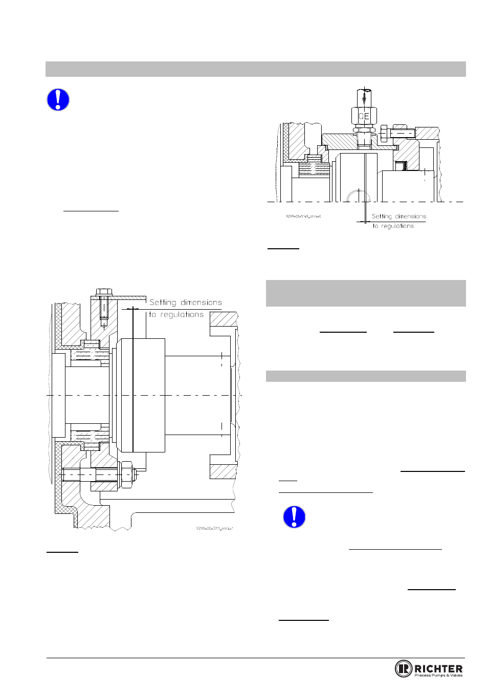
The wear on the rotary ring can be readily seen by the
increased size of the set dimension in many makes.
See Figure 1 and 2.
The external mechanical seals are to be replaced
before the wear on the rotary ring become so great
that the pressing forces are no longer sufficient
as a result major leaks occur.
Often marks on the mechanical seal indicate the
admissible wear.
Figure 1 External, single mechanical seal with
and without lip seal
Figure 2 Single mechanical seal with lip seal
and quench
5.1 External, single mechanical
seal
Dismantling can be checked using the sectional
drawings in Section 7.2 and Section 9 in the
installation and operating manual SCK, also the
available components.
5.1.1 Dismantling
Remove seal guard 685.
Undo setscrews 904/1 of the distance bush 543.
Undo attachment screws of the rotating unit 470/2.
Undo screws of bearing pedestal 330 / back plate
161
and, with the mating ring 475/1 and the mating
ring adapter 487 still mounted, move up to the
impeller with light hammer blows (plastic hammer).
For design of back plate, see Section 4.2 and
7.7.4
in the installation and operating manual SCK.
Bearing pedestal group 3:
Labyrinth disc 555 must be secured with two bolts
prior to the dismantling
of the impeller.
For this purpose there are 2 bores Ø5mm
in the bearing pedestal. The double
mechanical seal is relieved of pressure as a result.
See dismantling in Sections 7.7.1 and 7.7.5 in the
installation and operating manual SCK.
Undo impeller 230 with a strap wrench or
assembly wrench. Right-hand thread.
For assembly aid for impeller, see Section 10.1 in
the installation and operating manual SCK.
See also installation and operating manual SCK,
Section 7.7.1
.
Unscrew the impeller 230 completely.