Page 37 – HF scientific Micro200BW Turbidimeter - 0-100 NTU User Manual
Page 49
MICRO 200 BW 0-10 & 0-100 NTU (05/05)
Rev. 3.4
3-35/64
(90)
4-21/64
(110)
8-13/64
(224)
7-3/32
(180)
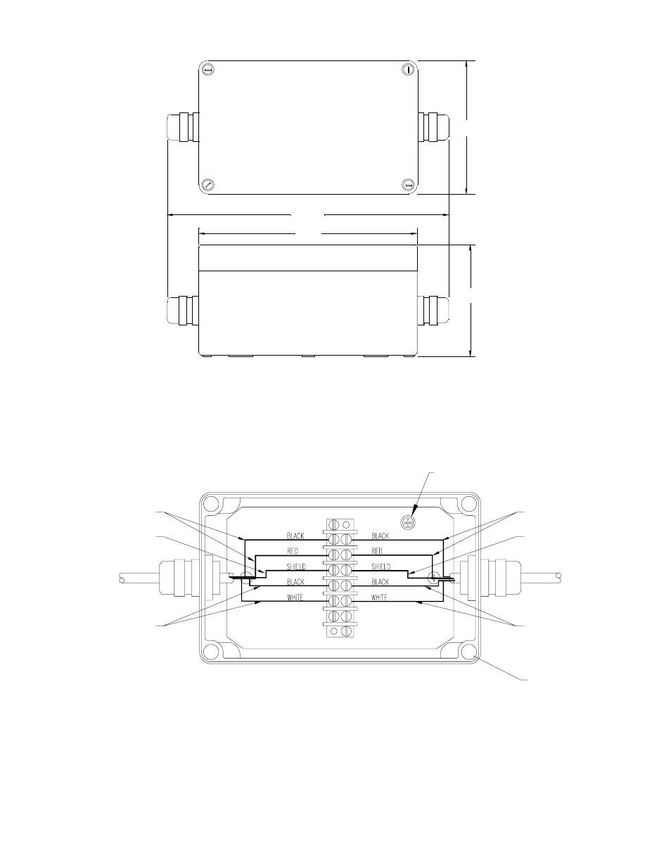
Figure 18
Junction Box Outline
Figure 19
Junction Box Wiring Diagram
MOUNTING HOLES
4-PLACES
CABLE PAIR
CABLE PAIR
NOTES:
USE ONLY 2-PAIR SHIELDED
CABLE TYPE 6052C.
FROM SENSOR
TO ANALYZER
2-SHIELD WIRES
CABLE PAIR
2-SHIELD WIRES
CABLE PAIR
NOT USED
Page 37
This manual is related to the following products: