HF scientific Micro200BW Turbidimeter - 0-100 NTU User Manual
Page 43
MICRO 200 BW 0-10 & 0-100 NTU (05/05)
Rev. 3.4
Page 31
7.0 TROUBLESHOOTING
7.1 GENERAL NOTES
Service and technical support are available from the manufacturer, HF scientific inc. from 8:00 AM to 4:00 PM Eastern
Standard Time.
The following Table will supply fundamental troubleshooting information. The Guide assumes that the controls and
functions of the instrument are used correctly. The intention of the guide is to eliminate common faults, not to
troubleshoot down to component level.
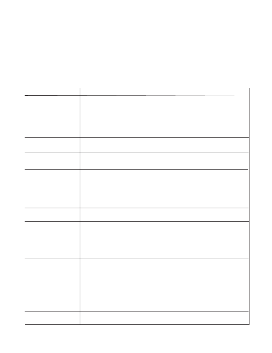
GUIDE TO FUNDAMENTAL TROUBLESHOOTING
SYMPTOM
SOLUTION
Display not lit.
1. Make sure that the unit is plugged in and turned on. Make certain that your power
source is providing the correct voltage.
2. Check analyzer fuse. Refer to page 7 for correct fuse size and instructions for changing.
3. Shut off power for about five seconds and then turn it back on. This will initiate a power
on reset.
4. If none of the above steps correct the problem, contact HF scientific, inc. service dept.
for additional support.
Instrument not
1. If sensor cable was removed from the analyzer, check wiring connections.
functioning correctly.
Cannot leave menu.
1. Invalid parameters may have been inadvertently set. Examples of this are a bad
time or date or the lower limit set higher than the upper limit. Check the screen
and change any invalid numbers.
Display response slow.
1. Select a lower averaging time.
Sensor alarm on.
1. Replace the lamp module.
2. Check the connection at the sensor.
3. The turbidity may be too high. If you are on the low range, switch to the higher range.
4. Replace the sensor. If you have a spare sensor or another MICRO 200 BW you may
use the alternate sensor to determine if the sensor in question is defective.
Readings lower than
1. Recalibrate with known good standards.
expected.
Readings higher than
1. Check the flow through cuvette. If it has dirt on either the inside or outside or is
expected.
scratched, clean the cuvette or replace it.
2. Check for condensation on the outside of the cuvette. If condensation is present either
the desiccant tray needs replacement or the vaporpurge system of the sensor is
defective. Replace the desiccant or the sensor.
3. Recalibrate the sensor with known good standards.
Readings erratic.
To check if the erratic readings are due to sample measurement or a problem with the
instrument, remove the flow through unit and place a light shield over the sample well.
This may be left for a period of time and the graphic history observed later. If the graph
shows instability the MICRO 200 BW has a problem. Call HF scientific service dept.
If the graph is stable there is a problem with the sample being measured. See the
following for suggested corrections.
1. Check for debris in flow through cuvette. Clean out as required.
2. Increase back pressure with flow control valve. This will keep air in solution.
Analyzer Displays
1. "0-10 range 10 NTU calibrate" should only be performed with a 10 NTU standard in
sensor well.
"Frequency Error"