Elev ator aileron rudder, As3x control direction test – E-flite Carbon-Z Splendor BNF Basic User Manual
Page 9
EN
Assemble the aircraft and bind your transmitter to the receiver
before performing this Test.
Activate the AS3X system by advancing the throttle to 25%, then
fully lowering the throttle.
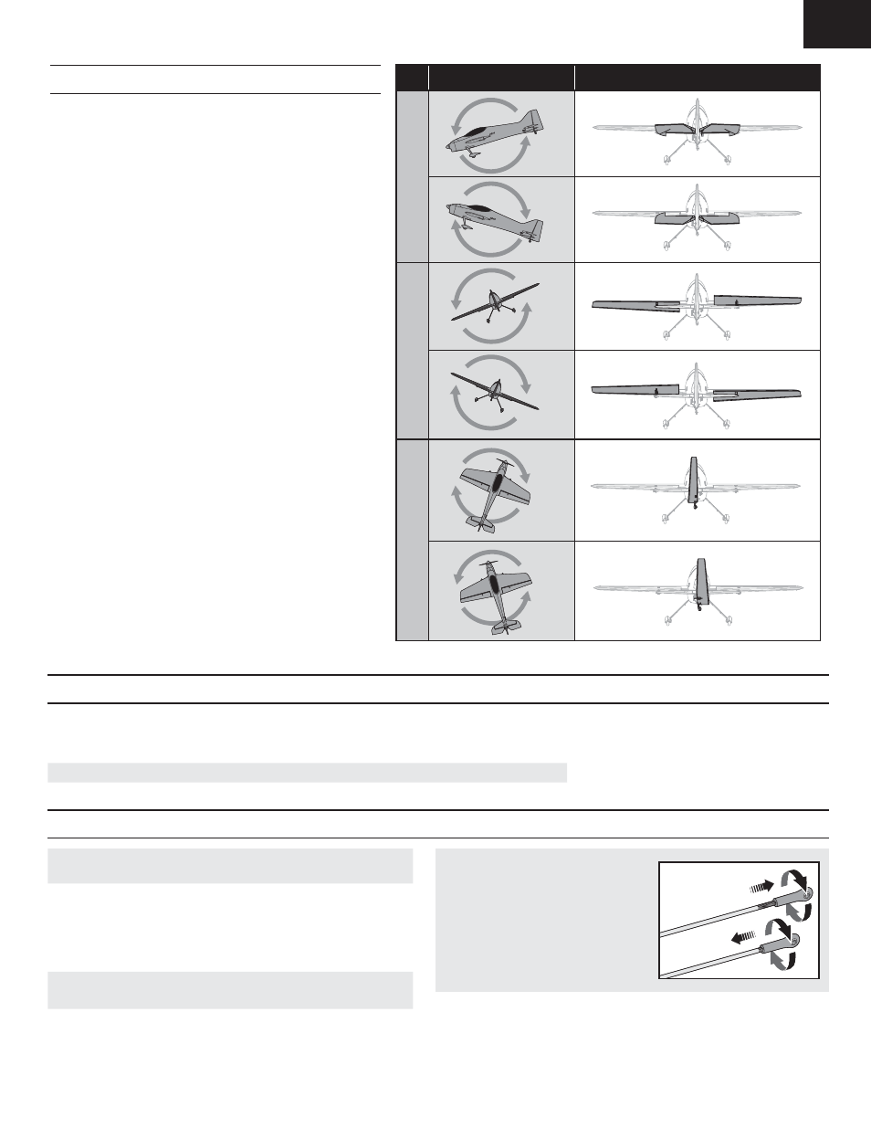
Move the aircraft as shown to ensure the AS3X system moves the
control surfaces in their proper direction. If the control surfaces do
not respond as shown, do not fly the aircraft. Refer to the receiver
manual for more information.
Once the AS3X system is active, the control surfaces may move
rapidly on the aircraft. This is normal. AS3X will remain active until
the battery is disconnected.
Aircraft movement
AS3X Reaction
Elev
ator
Aileron
Rudder
AS3X Control Direction Test
Move the controls on the transmitter to make sure the aircraft control surfaces move correctly and in the proper direction or reverse a servo. After performing the
Control Test, correctly set the failsafe. Make sure the transmitter controls are at neutral and the throttle and throttle trim are in the low position, then rebind the
model to your transmitter. If the receiver loses its connection to the transmitter, the failsafe will drive the servos to the settings made at binding.
NOTICE: In your transmiter, ensure Channel 5 servo is in NORMAL position for proper AS3X funcionality.
Control Direction Test
Control Surface Centering, Transmitter and Receiver Operation
IMPORTANT: Perform the Control Direction Test before performing control
surface centering.
Control Surface Centering and Adjusting a Linkage
Tip: While AS3X is inactive (before advancing the throttle), mechanically center
the control surfaces.
IMPORTANT: Correct operation of the AS3X system requires sub-trim and
trim at 0.
After binding a transmitter to the model receiver, set the trims and sub-trims to
0, ensure the servo arms are in the correct positions, then adjust the linkages
to center the control surfaces.
• Turn the linkage clockwise or counter-
clockwise until the contol surface is
entered.
• Attach the linkage to the servo arm or
control horn after adjustment.
Tip: If using more than 8 clicks of flight trim, mechanically adjust the linkage
so less trim is needed, or AS3X operation may be affected.
Tip: Use needle-nose pliers or ball link pliers (RV01005) to remove or install a
link on a control horn
.
9