Caution – Burnham Series 2B User Manual
Page 6
A. Allowable loss of pressure to assure a burner
manifold pressure of 3½" (8.9cm) water for natural
gas.
B. Supply of gas to be provided in cubic feet.
C. Length of piping and number of fittings.
D. Specific gravity of gas.
E. Correction factor for specific gravity.
9.
BOILER PIPING
CAUTION
Failure to properly pipe boiler may result in
improper operation and damage to boiler or
building.
A. CLEARANCES - hot water pipes do not require
clearance from combustible construction.
B. Install drain valve and safety relief valve as shown
in Figures 1 and 3. Note - Safety relief valve must
be in vertical position.
C. Pipe safety relief valve discharge to floor.
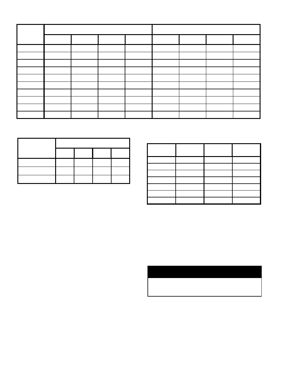
Table 1: Maximum Capacity of Schedule 0 Pipe in CFH For Natural Gas Pressures of ½ psig or Less
Table 2: Equivalent Length of Fittings
Table 3: Specific Gravity Correction Factors for
Natural Gas
This piping is to be supplied by the installer and must
include a trap, a ground joint union and a manual
shutoff valve upstream of the gas control assembly
outside of the jacket when codes require, see Figure 1.
A pipe thread compound resistant to the action of
liquefied petroleum gases should be applied to all
threaded joints in the gas piping. Pressure testing of the
Gas Supply Piping Boiler and its connections is
required before placing the boiler in operation.
The boiler and shutoff valve must be disconnected from
the gas supply piping system during any pressure
testing at pressures greater than ½ psig (3.5kPa).
The boiler must be isolated from the gas supply piping
system by closing its individual manual shutoff valve
during any pressure testing of the gas supply piping
system at pressures equal to or less than ½ psig
(3.5kPa).
RECOMMENDED SIZING OF GAS SUPPLY
PIPING TO BOILER FOR NATURAL GAS - shall
be such as to provide the required supply of gas without
undue loss of pressure between meter and the boiler.
Gas supply piping should be sized in accordance with
the Tables 1, 2 and 3. The following shall be taken into
account:
Length
[Feet]
0.3 Inch w.c. Pressure Drop
0.5 Inch w.c. Pressure Drop
½
¾
1
1¼
½
¾
1
1¼
10
132
278
520
1,050
175
360
680
1,400
20
92
190
350
730
120
250
465
950
30
73
152
285
590
97
200
375
770
40
63
130
245
500
82
170
320
660
50
56
115
215
440
73
151
285
580
60
50
105
195
400
66
138
260
530
70
46
96
180
370
61
125
240
490
80
43
90
170
350
57
118
220
460
90
40
84
160
320
53
110
205
430
100
38
79
150
305
50
103
195
400
Fitting
Nominal Pipe Size
½
¾
1
1¼
45° Ell
0.7
1
1.2
1.6
90° Ell
1.6
2.1
2.6
3.5
Tee (As Elbow)
3.1
4.1
5.2
6.9
Specific
Gravity
Correction
Factor
Specific
Gravity
Correction
Factor
0.50
1.10
1.30
1.07
0.55
1.04
1.40
1.04
0.60
1.00
1.50
1.00
0.65
0.96
1.60
0.97
0.70
0.93
1.70
0.94
0.75
0.90
---
---
0.80
0.87
---
---