Bunn CWA-APS User Manual
Page 22
Page 22
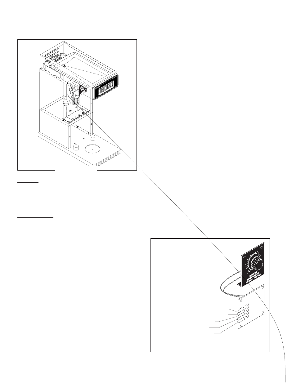
FIG. 17 TIMER TERMINALS
P1472
TL1 WHI/RED from ON/OFF Switch(1)
TL2 RED to Terminal Block (Red Insert)
TL3 WHI/ORN from Start Switch
TL4 WHI/GRN from Solenoid
TL5 WHI/YEL from Start Switch
TIMER (Early Models)
FIG. 16 TIMER
P1468.40
Location:
The timer is located inside the front of the trunk on
the component bracket. It consists of the dial plate and
circuit board.
Test Procedure:
1. Disconnect the brewer from the power source.
2. Remove the wires from terminals TL3, TL4, & TL5
of the timer and rotate the dial fully counterclock-
wise.
2. With a voltmeter, check the voltage across termi-
nals TL1 and TL2 when the ON/OFF switch is in the
“ON” (upper) position. Connect the brewer to the
power source. The indication must be 240 volts ac.
3. Disconnect the brewer from the power source.
If voltage is present as described, proceed to #4.
If voltage is not present as described, refer to the
Wiring Diagram
and check the wiring harness.
4. Check for continuity across the white/orange wire
and white/yellow wire when the START switch is
held in the lower position.
If continuity is present as described, reconnect the
wires to terminals TL3, TL4, & TL5 of the timer board
and proceed to #5.