Prepare the burner, Inspect/prepare installation site, Caution – Beckett NX User Manual
Page 6
Page 6
RWB 6104 BNX R02
Prepare the Burner
General
In most cases, the burner is ready to mount to the
appliance. There can be situations where the burn-
er needs to be reconfi gured to perform properly in
the appliance. Review the appliance manufactur-
er’s specifi cations prior to installing to determine if
any modifi cation is required to properly confi gure
the burner.
Instruction on how to perform the following burner
preparation tasks can be found in the Professional
Maintenance section.
Remove / install burner nozzle
Check head/air adjusting plate
Low Firing Rate Baffl e (If specifi ed)
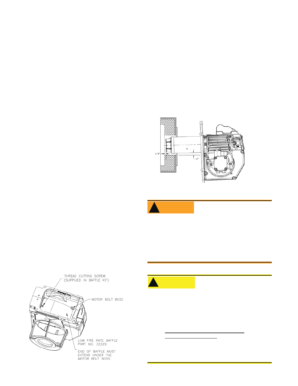
The NX Low Firing Rate Baffl e (LFRB), refer to Fig-
ure 2, reduces the burner airfl ow and pressure. Re-
fer to the appliance manufacturer’s instructions or
the Beckett OEM Specifi cation Guide part number
6711. To avoid poor burner performance, do not
omit the baffl e when specifi ed or install the baffl e
when not specifi ed.
Note:
The Low Firing Rate Baffl e may have been factory
installed. If fi eld installation is required, insert the
Low Fire Rate Baffl e into the housing, aligning the
mounting screw hole with the notched hole in the
burner housing. Make note that the curved end
of the baffl e should be below the motor bolt boss.
Tighten the thread cutting screw to 12-24 in-lbs.
•
•
•
•
Figure 2. – Mounting Low Fire Rate Baffl e in
burner housing.
SK9698
Inspect/Prepare Installation Site
Figure 3. – Mounting Burner in Appliance
SK9668
Mount Burner on Appliance
Verify that the air tube installed on the burner pro-
vides the correct insertion depth. Refer to Figure
3.
The end of the air tube should normally be 1/4”
back from the inside wall of the combustion cham-
ber. Never allow the leading edge of the retention
ring to extend into the chamber, unless otherwise
specifi ed by the appliance manufacturer.
Bolt the burner to the appliance using the factory-
welded fl ange.
•
The burner is shipped without the by-pass plug in-
stalled.
Install the by-pass plug in two-pipe oil supply systems
ONLY.
•
•
Failure to comply could cause immediate pump
seal failure, pressurized oil leakage and the po-
tential for a fi re and injury hazard.
Do Not Install By-pass Plug
with 1-Pipe System
WARNING
!
Connect Fuel Lines
•
The oil supply inlet pressure to the burner cannot
exceed 3 psig.
Insure that a pressure limiting device is installed
in accordance with the latest edition of NFPA 31.
Do not install valves in return line.
Gravity Feed Systems: Always install an anit-
siphon valve in the oil supply line or a solenoid
valve (RWB Part # 2182602U) in the pump/noz-
zle discharge tubing to provide backup oil fl ow
cut-off protection.
•
•
•
•
Damage to the fi lter or pump seals could cause
oil leakage and a fi re hazard.
Oil Supply Pressure
Control Required
!
!
CAUTION