Rinsing measuring vessel, Rinsing transfer tubing, Evaluation – Metrohm MVA-21 User Manual
Page 9: Substances, Standards, Calibration
Application Bulletin 403/1 e
Installation instruction for MVA-21
4.1.5. Rinsing measuring vessel
After each sample the measuring vessel need to be rinsed
with deionized water. The rinsing and draining times depend
on the total volume used in the determination.
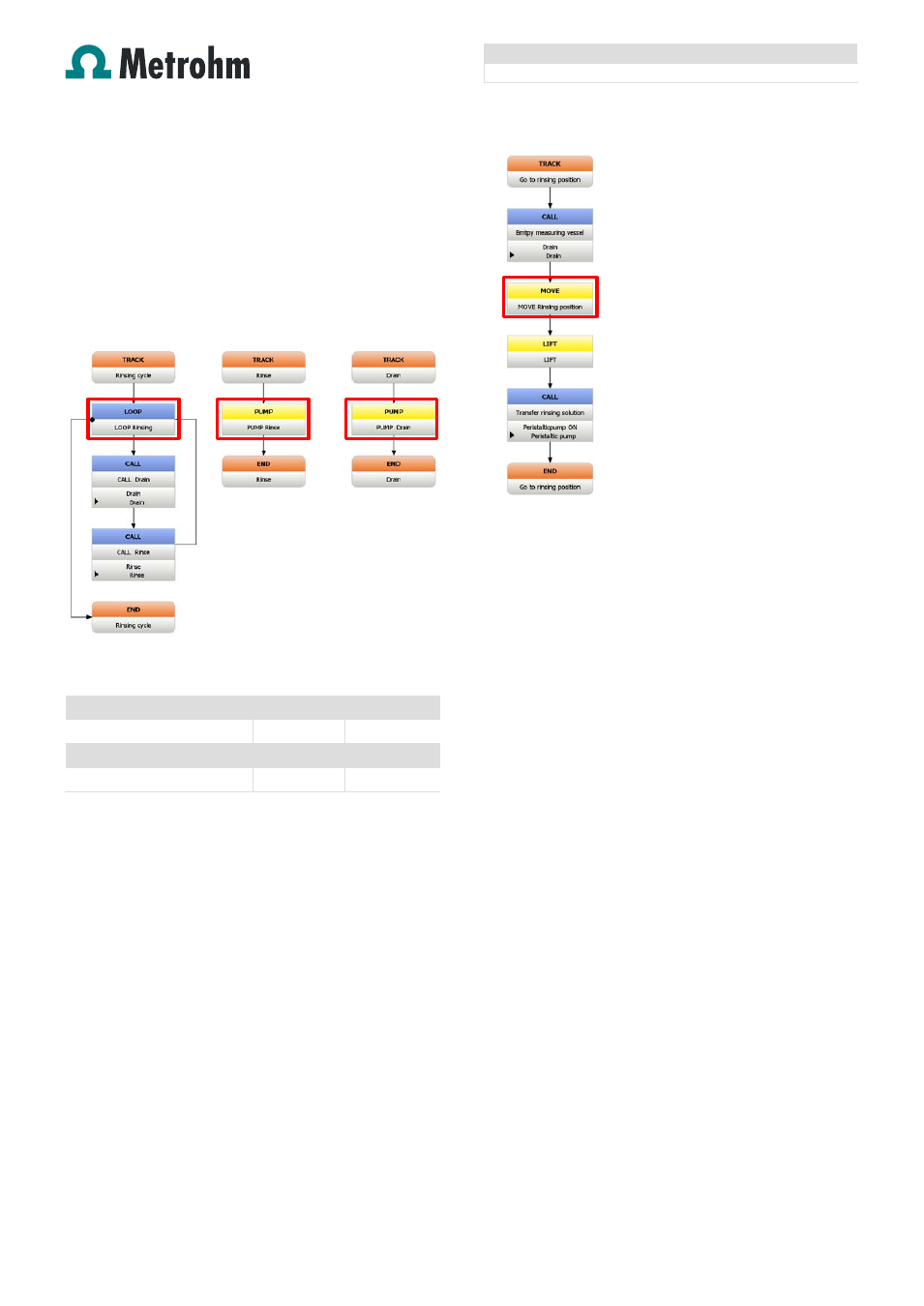
If the method templates are used, the rinsing and draining
times are defined in the corresponding PUMP
commands in
the TRACK
–R
INSE
and
TRACK
–
D
RAIN
. The number of
rinsing cycles is defined in the command LOOP
–
LOOP
R
INSING
in the TRACK
–
R
INSING CYCLES
.
Fig 11: Method snippet TRACK
–
R
INSING CYCLE
Examples for rinsing and draining times:
Cell volume
50 mL
100 mL
Number of rinsing cycles
2
2
Draining time [s]
35
50
Rinsing time [s]
9
18
Please note! The device assigned to the commands PUMP
–
PUMP
R
INSE
und PUPM
–
PUMP
D
RAIN
need to be the
858 Professional Sample Processor, since the 843 Pump
Station is connected to and controlled from the sample
changer.
4.1.6. Rinsing transfer tubing
This only applies for the brightener determination by MLAT!
After each sample the transfer tubing from the 858
Professional Sample Processor to the measuring vessel of
the 894 Professional CVS need to be rinsed with deionized
water. The rinsing solution is placed in a vial on the rack of
the 858 Professional Sample Processor. The position of the
rinsing solution relative to the sample position is defined in
the
TRACK
–
G
O TO RINSING POSITION
in the
command MOVE
–
MOVE
R
INSING POSITION
.
Fig 12: Method snippet TRACK
–
G
O TO RINSING POSITION
The position of the rinsing solution is defined as «sample
position + 28». This means the outer circle on the rack
6.2041.450 is used for the sample the inner circle for the
rinsing solution
The transfer time for the rinsing solution corresponds to the
sample transfer time defined in the TRACK
–
P
ERISTALTIC
PUMP
in the
command PUMP
–
P
ERISTALTIC PUMP
ON.
4.2.
Evaluation
Settings regarding evaluation and documentation of the
determination are located in the «Evaluation» part of the
method. The templates already include all necessary
settings to determine brightener or suppressor concentration
in an acid copper bath. If modifications however should be
necessary, here is where important parameters are found:
4.2.1. Substances
In the «Substances» part settings for peak recognition and
baseline parameters are defined.
4.2.2. Standards
In the «Standards» part the concentration of the used
standard solution is defined.
4.2.3. Calibration
In the «Calibration» part the calibration method, such as DT
or MLAT, is defined as well as the regression type.
Page 9 of 12