5 measurement of the insulation resistance, Measurement of the insulation resistance, Fig. 4: unloaded potential source – Metrohm 767 Calibrated Reference User Manual
Page 9: Fig. 5: on-load potential source
2 General instrument handling
767 Calibrated Reference Instructions for Use
5
Ri
E
R
input
Fig. 4: Unloaded potential source
Ri
E
R
input
Rx
Fig. 5: On-load potential source
If the electrode is now calibrated, i.e. the electrode parameters are de-
termined, then the instrument is in reality being adapted to the elec-
trode. This means that the previously determined error will also be
compensated. The measurement will again be correct.
Why make so much fuss when everything is back in order?
One must be aware of the fact that such contaminations form an ex-
tremely unstable resistance, whose value alters with the atmospheric
humidity, temperature and many other chance occurrences. The resis-
tance can therefore vary greatly. Together with R
i
, which is strongly de-
pendent on the temperature, this gives a very unstable potential divider.
This is then no longer compensated, at best during the next electrode
calibration (and therefore again by chance). Because this error is cov-
ered up again at every calibration it is often not noticed for a long time,
although it produces false (and above all unstable) results.
From this it can be seen that a constant additional monitoring of the
high impedance of pH Meters and Titrators must be a basic concern of
quality assurance. However, this only makes sense when the most ex-
posed element, the sensor cable, is included in the monitoring process.
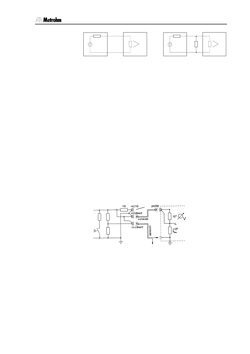
2.5 Measurement of the insulation resistance
Explanation for the steps 9-12, section 3.2.1 U/mV, pH.
Fig. 6: Measurement of the insulation resistance versus earthing
R
Isol
of the instrument to check via insulation of 6.2104.020 (6.2150.040)
cable and socket (5) is in parallel with R
2
using this interconnection.
With R
Isol
ok, e.g. > 10
8
Ω, there is no change in the display of the in-
strument to check.
R1
R2
(6)
(4)