Assembly, Operating the jig saw, Operating the laser – Black & Decker JS700L User Manual
Page 2: Save these instructions, Ic j, Ab c d k
Motor
Be sure your power supply agrees with nameplate marking. 120 Volts AC only means
your tool will operate on standard 60 Hz household power. Do not operate AC tools on DC.
A rating of 120 volts AC/DC means that you tool will operate on standard 60 Hz AC or DC
power. This information is printed on the nameplate. Lower voltage will cause loss of power
and can result in over-heating. All Black & Decker tools are factory-tested; if this tool does
not operate, check the power supply.
SAVE THESE INSTRUCTIONS
Assembly
WARNING: Sharp blade. To prevent accidental operation, turn off and unplug saw
before performing the following operations. Failure to do this could result in serious
personal injury.
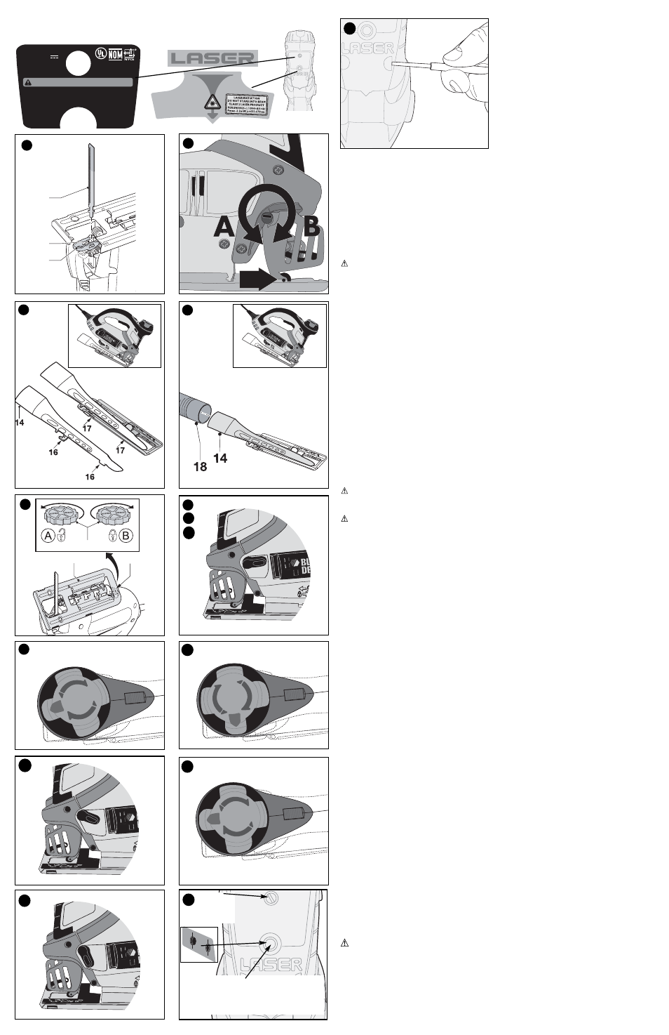
Fitting the saw blade (fig. A)
- Hold the saw blade (7) as shown, with teeth facing forward.
- Push the lever (4) downwards.
- Insert the shank of the saw blade into the blade holder (15) as far as it will go.
- Release the lever.
- Adjust the blade support roller as described below.
AccuCut
TM
blade support roller (fig. B)
After fitting the blade, you need to adjust the blade support roller (5).
Screwdriver Method
- Turn the slotted blade support adjustment screw (6) in direction A.
- Slide the blade support roller against the rear of the blade. The blade must locate
in the central recess of the roller.
- Turn the blade support adjustment screw in direction B to lock the blade support in place.
Tool Free Method
- The blade support roller can be adjusted in a “tool free” manner, by turning the scrolling
knob (8) so that the adjustment screw is rotated around to the front of the unit where it can
be turned by hand.
Connecting a vacuum cleaner to the tool (fig. C & D)
- Align the dust extraction adaptor (14) with the saw shoe as shown.
- Insert the ribs (16) into the slots (17).
- Pull the adaptor towards the rear of the jigsaw to secure.
- Connect the vacuum cleaner hose (18) (not supplied) to the adaptor.
- Dust extraction is not possible when making bevel cuts.
WARNING: Fire Hazard. Do not use vacuum adapter when cutting metal. Metal
filings will be hot and could cause a fire in the vacuum container.
Operating the Jig Saw
WARNING: Laceration Hazard. To prevent loss of control, never use the tool when
the saw shoe is loose or removed. Failure to do this could result in serious personal injury.
Adjusting the shoe plate for bevel cuts (fig. E)
The shoe plate can be set to a left or right bevel angle of up to 45°.
- Turn the locking knob (11) in direction A to release the shoe plate (10).
- Pull the shoe plate (10) backwards and set it to the required angle. You can use the
scale or a protractor to check the angle.
- Turn the locking knob (11) in direction B to lock the shoe plate in place.
To reset the shoe plate for straight cuts:
- Turn the locking knob (11) in direction A to release the shoe plate (10).
- Pull the shoe plate backwards and set it to an angle of approximately 0.
- Push the shoe plate forward.
- Turn the locking knob (11) in direction B to lock the shoe plate in place. Make sure that
the shoe plate is supported by the guide ribs.
Variable speed control
- Set the variable speed control knob (3) to the required speed range. Use a high speed
for wood, medium speed for aluminum and PVC and low speed for metals other than
aluminum.
Switching On and Off
- To switch the tool on, press the on/off switch (1).
- For continuous operation, press the lock-on button (2) and release the on/off switch.
- To switch the tool off, release the on/off switch. To switch the tool off, when in continuous
operation, press the on/off switch once more and release it.
Using the mode selector
The mode selector (9) can set in 3 positions
1. Scrolling position (figs F and G) - this position allows the scroller knob (8) to be
rotated for intricate and accurate sawing. (In this position there is no orbital action.)
It is recommended to use scroller blades when in this mode.
2. Straight cutting position (figs Ha, Hb and Hc ) this position turns off orbital action and
locks the scroller knob to prevent its rotation. The scroller knob can be locked in any
of 4 positions for straight cutting.
Method of engagement:
a. Turn the Mode Selector to the scrolling position.
b. Rotate the scroller knob to the desired position (this can be any of 4 positions -
the blade can point forwards, reverse, left or right).
c. Turn the Mode Selector to the neutral position. (In this position the Scroller Knob
cannot be turned).
3. Orbital Action Position (figs Ia, Ib and Ic) - this position switches on the orbital action
for fast and efficient straight cuts. This mode can only be selected with the blade
pointing forwards.
Method of engagement:
a. Turn the mode selector to the scrolling position.
b. Rotate the scroller knob to point the blade forwards.
c. Turn the Mode Selector to the orbital position. (In this position the Scroller Knob
cannot be turned).
Operating the Laser
Installing the batteries
Detach the laser from the jig saw by removing the screw shown in figure J and pulling laser
forward. Insert 2 fresh 1.5 volt AAA alkaline batteries making sure to match (+) and (-)
terminals correctly. Reattach the laser.
WARNING: Batteries can explode, or leak, and can cause injury or fire. To reduce this
risk:
• Carefully follow all instructions and warnings on the battery label and package. • Always
insert batteries correctly with regard to polarity (+ and -), marked on the battery and the
equipment. • Do not short battery terminals. • Do not charge batteries. • Do not mix old
and new batteries. Replace all of them at the same time with new batteries of the same
brand and type. • Remove dead batteries immediately and dispose of per local codes. •
Do not dispose of batteries in fire. • Keep batteries out of reach of children. • Remove bat-
teries if the device will not be used for several months.
11
10
11
E
max
6
max
6
F
G
Hb
max
6
Hc
Ib
Ha
Ia
Ic
J
15
4
7
A
B
C
D
K
COMPLIES
WITH 21CFR
PARTS 1040.10 AND
1040.11 EXCEPT FOR
DEVIATIONS PURSUANT
TO LASER NOTICE NO.50,
DATED JULY 26,2001.
588808-01 Made in China
Type 1 3V DC
Use with compatible
B&D Jig Saws.
Pats. Pend.
1-800-54-HOW-TO
Black & Decker (U.S.) Inc.,
Towson, MD 21286 U.S.A.
LISTED
406A
WARNING/ADVERTENCIA/AVERTISSEMENT
To reduce the risk of injury,
user must read and
understand instruction
manual. Use (2) AAA
size alkaline batteries.
À titre préventif,
lire le guide.
Para reducir el riesgo de
lesiones, el usuario debe
leer y entender el
manual de
instrucciones.
Utilice (2) baterías
alcalinas AAA.
ON/OFF
For your convenience and safety, the following labels are on the laser.
Pour plus de commodité et de sécurité, les étiquettes suivantes sont apposées sur le laser.
Para su comodidad y seguridad, el láser incluye las siguientes etiquetas.
Laser On/Off Button
Bouton marche/arrêt du laser
Botón de encendido/apagado del láser
Screw
Vis
Tornillo
ON
OFF