Changing the control mode of the transmitter – DJI Phantom Advanced Manual User Manual
Page 3
©2013
DJI Innovations. All Rights Reserved.
5 |
A4
Changing the Control Mode of the Transmitter
You can change the operation mode of the transmitter according to the following procedures if necessary.
(The
operation mode of Mode1 and Mode2 are shown as below.
)
Make sure to carry out the A5 Transmitter Calibration, if the Control Mode of the Transmitter is changed.
1. Remove the right Throttle Ratchet plate and the Ratchet Nut. Assemble the Ratchet Nut to the Nut Hole
Location
,and fix the Throttle Ratchet onto the Ratchet Nut and the Screw Hole Location. Adjust the
screw height of the Throttle Support to change the tension, so as to give you the required operating feel.
2. Remove the left Centering Unit and the Centering Spring.
Assemble them to the corresponding position
of the Right part (Close to the middle location of the transmitter).
Then adjust the height of the Adjusting
Screw, so as to give you the required operating feel. (Note: Be careful not to excessively tension the
spring when moving and fixing, to avoid damage.)
3. Exchange the connectors of Channel 2(AIN2)and Channel 3 (AIN3). (Note: Take care about the
connector direction.
)
Mode2
1
2
3
4
5
6
8
9
NO.
Name
1 Screw
Hole
Location
2
Centering Unit
3 Adjusting
Screw
4
Ratchet Nut
5 Throttle
Ratchet
6
3rd Channel
7 2nd
Channel
8
Centering Spring
9
Nut Hole Loc tion
Mode1: Throttle, it cannot hold the central position when released.
Roll, it can return to the central position when released.
Pitch, it can return to the central position when released.
Yaw, it can return to the central position when released.
Model2:
Throttle, it cannot hold the central position when released.
Roll, it can return to the central position when released.
Pitch, it can return to the central position when released.
Yaw, it can return to the central position when released.
©2013
DJI Innovations. All Rights Reserved.
6 |
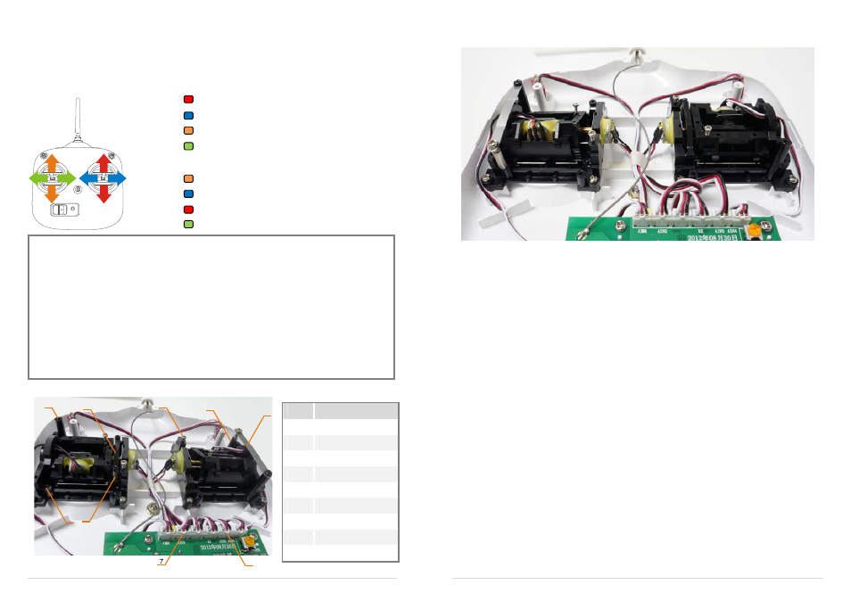
The following figure shows the successful change of transmitter mode to Mode 1.
Mode1