Bloomfield 9454 User Manual
Page 12
OPERATION (continued)
NOTE: Hoppers and
motors for various products
are essentially identical.
In a cold / hot dispensing
mode, the cold product
must be placed in the left
dispenser only. Otherwise,
product may be placed in
and dispensed from either
hopper.
SUGGESTION: For easy
identification of the hopper
contents, a 2” strip of
“frosty” tape placed on the
front of the hopper is a
handy place to write the
contents name.
NOTE:
Keep front door closed
when operating dispenser.
This prevents excessive
steam and humidity from
entering the hopper
compartment.
FILL PRODUCT HOPPERS
1. Hoppers and covers should be thoroughly washed and dried.
Examine hoppers for completeness and proper assembly prior to
placing them into service.
2. Fill the hopper with the desired product powder and install the
hopper cover.
3. Apply the appropriate label to the door assembly, above the touch
pad keys, from the provided sheet of labels. Additional labels are
available from your Authorized Bloomfield Distributor.
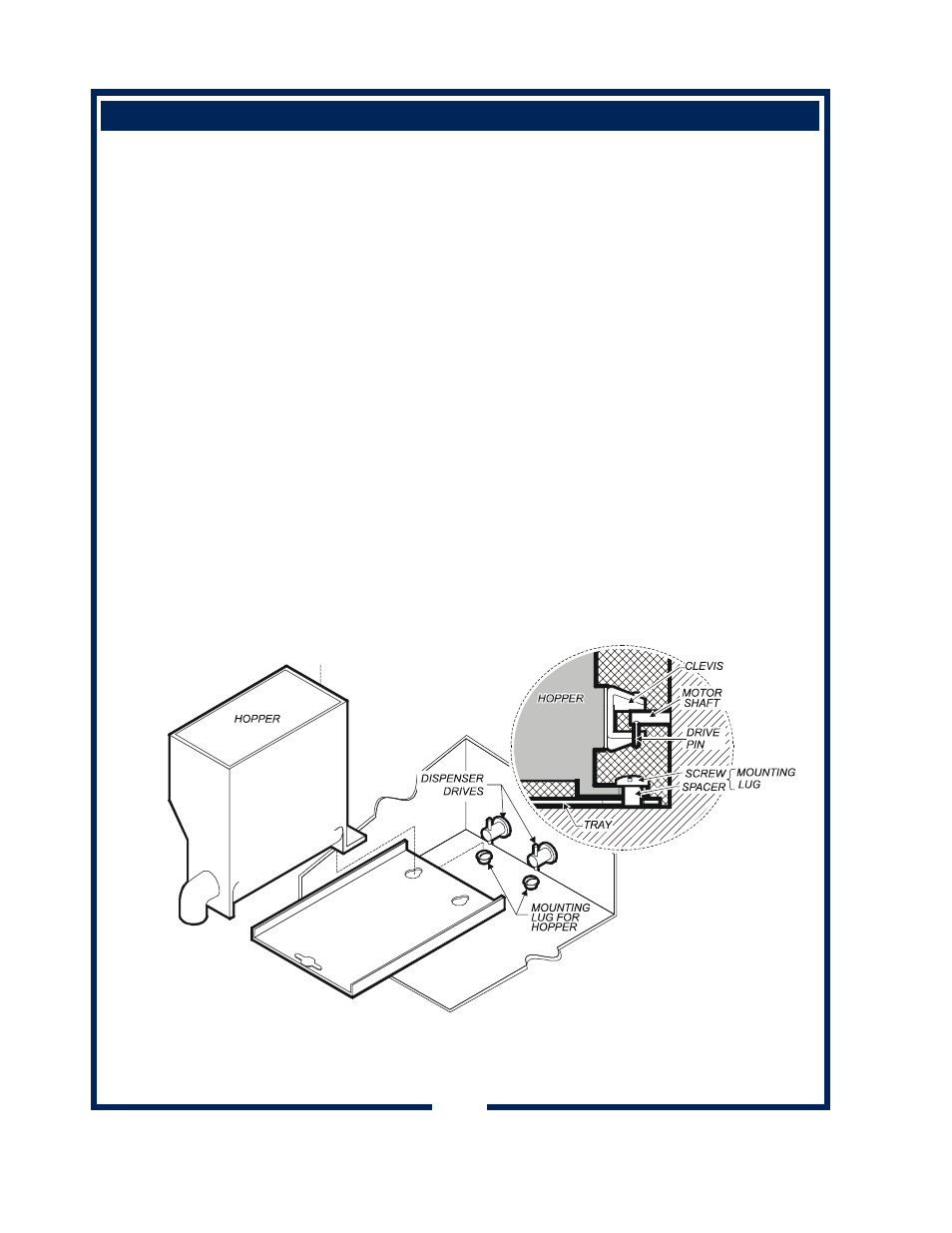
INSTALL PRODUCT HOPPERS
1. Manually position the U-Shaped clevis HORIZONTALLY so that it
will engage with the drive motor drive pin when it is installed in the
hopper compartment. See illustration below.
2. Press the appropriate selection key to position the motor drive pin
VERTICALLY so that it will engage with the hopper clevis without
interfering with the hopper sliding to its full rear position.
3. Insert the hopper mounting tray by setting it over the mounting lugs,
then pulling it as far forward as it will go. The tray should lay flat
against the bottom of the dispenser inner cavity.
4. Slide the hopper against the side rail of the mounting plate. Slightly
lift up the front of the hopper while pushing it back until the back
edge of the hopper slips under the mounting lug on the rear floor of
the inner compartment.
5. Place cup under blender spout, dispense and discard a serving
from each hopper to prime the system.
10
NOTE: In the illustration,
the clevis and drive pin
are shown rotated and
engaged. To install the
hopper, the clevis should
be horizontal, and the
drive pin vertical.