Setup, Page 7, Figure 2: the rear connections – Blizzard Lighting RGBAW ToughStick (Rev C) User Manual
Page 7
Page 7
ToughSTICK™ RGBAW Manual - Rev. C
Copyright (c) 2012 Blizzard Lighting, LLC
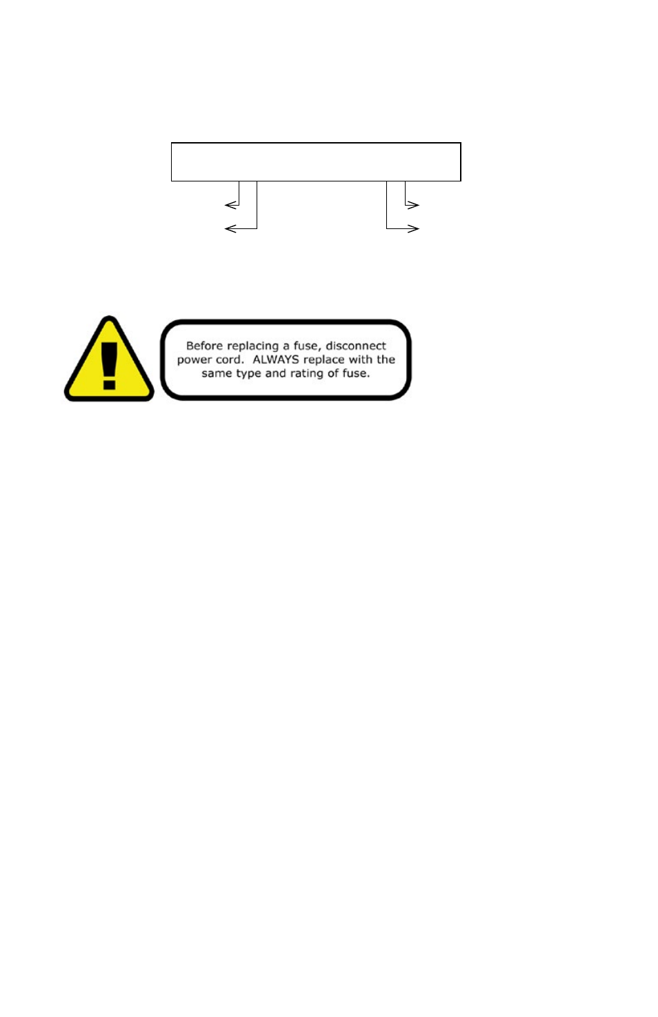
Figure 2: The Rear Connections
AC Power In
3-Pin
DMX512 In
AC Power Out
3-Pin
DMX512 Out
Extended, waterproof AC power and 3-pin DMX connections.
3. SETUP
Fuse Replacement
CAUTION! The ToughSTICK™ RGBAW utilizes a high-output switch-mode power supply
with an internal fuse. Under normal operating conditions, the fuse should not require
replacement. The fuse is field replaceable, however it is an advanced procedure suited to
qualified individuals. Should your ToughSTICK™ fuse require replacement, please contact
Blizzard Lighting for instructions, or to return your unit for service.
Connecting A Bunch of ToughSTICK™ RGBAW Fixtures
You will need a serial data link to run light shows using a DMX-512 controller or to run
shows on two or more fixtures set to sync in master/slave operating mode. The combined
number of channels required by all the fixtures on a serial data link determines the number
of fixtures the data link can support.
Fixtures on a serial data link must be daisy chained in one single line. Also, connecting
more than 32 fixtures on one serial data link without the use of a DMX optically-isolated
splitter may result in deterioration of the digital DMX signal. The maximum recommended
cable-run distance is 500 meters (1640 ft). The maximum recommended number of
fixtures on a serial data link is 32 fixtures.
Data/DMX Cabling
To link fixtures together you’ll need data cables. You should use data-grade cables that can
carry a high quality signal and are less prone to electromagnetic interference.
For instance, Belden© 9841 meets the specifications for EIA RS-485 applications. Standard
microphone cables will “probably” be OK, but note that they cannot transmit DMX
data as reliably over long distances. In any event, the cable should have the following
characteristics:
2-conductor twisted pair plus a shield
Maximum capacitance between conductors – 30 pF/ft.
Maximum capacitance between conductor & shield – 55 pF/ft.
Maximum resistance of 20 ohms / 1000 ft.
Nominal impedance 100 – 140 ohms