Bird Technologies 61-89A-50 Series-Manual User Manual
Page 8
TXRX Systems Inc. Manual 7-9424-1 07/24/06 Page 2
cables at the filter. Two of cables run to a tee-
connector and one of the cables runs to the
card cage.
Rebanding 3 MHz systems. SB II
systems with an original 3 MHz
bandwidth use an extra filter in
series with the preselector on the
left side of the cabinet. This extra
filter is mounted horizontally at the top of the
cabinet. If you are rebanding a 3 MHz system to
a higher bandwidth system then the extra filter
will be removed permanently. Disconnect and
discard the cable between the left side prese-
lector and the extra filter.
5) Disconnect the signal sampler from the left side
filter. The two left side filters should be ready for
removal at this point.
6) Remove the screws which hold the filter mount-
ing plates to the cabinet mounting panel and
remove the filter assemblies from the cabinet.
Use care when removing the filters so as not to
damage any of the cables that are dangling in
the cabinet.
Rebanding 3 MHz systems. The
extra filter should be removed from
the cabinet first to provide addi-
tional room to maneuver the
remaining filters out of the cabinet.
7) Install the replacement filters in reverse order
making sure that the mounting plates are firmly
attached to the cabinet.
8) Reconnect three cables to the two filters on the
right side of the cabinet. Reconnect the cables
at the filter. Two of the cables run to a tee-con-
nector and one of the cables runs to the card
cage.
9) Reconnect the signal sampler to the right side
filter.
10) Reconnect three cables to the two filters on the
left side of the cabinet. Reconnect the cables
at the filter. Two of the cables run to a tee-con-
nector and one of the cables runs to the card
cage.
11) Reconnect the signal sampler to the left side
filter.
12) Verify that all filters and cables have been rein-
stalled properly, the booster should look
exactly as it did before installing the rebanding
kit.
13) Energize the booster and verify correct opera-
tion.
NOTE
NOTE
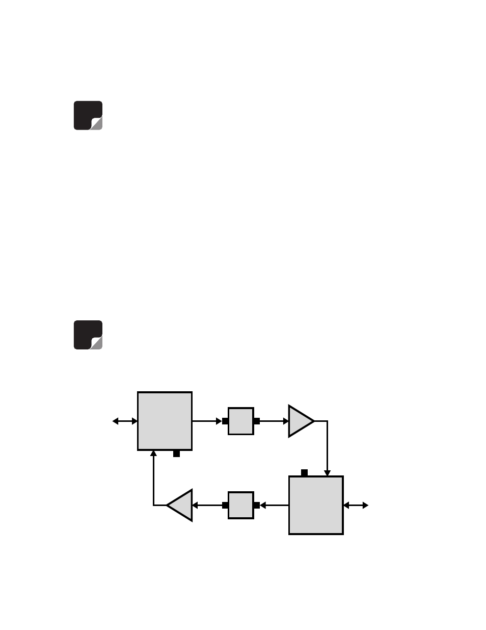
Signal
Sampler
Signal
Sampler
Circulator
Circulator
Duplexer
Duplexer
Amp
Amp
To
Cabinet
Connector
To
Cabinet
Connector
Figure 2: Simplified block diagram of the 18 MHZ SB II system.