General description, Types of 800 mhz sb ii re-banding kits, Procedure for non-18 mhz systems – Bird Technologies 61-89A-50 Series-Manual User Manual
Page 7
TXRX Systems Inc. Manual 7-9424-1 07/24/06 Page 1
GENERAL DESCRIPTION
These instructions are for rebanding 800 Mhz Sig-
nal Booster II systems in the field. Caution should
be taken not to drop the filters or sharply bump the
tuning rods located on the top of the filters, doing
so could result in de-tuning of the filters. The con-
version process consists of replacing the original
filters with new ones, adding a signal sampler if
required, replacing the Tee-connector as well as
several critical length cables. If there are any ques-
tions or concerns regarding the installation of this
rebanding kit, please contact the customer service
department at (716) 549-4700 extension 5044.
Types of 800 MHz SB II Re-banding kits
There are two types of rebanding kits available for
the 800 MHz SB II system. Which type of kit you
use will depend on whether your unit originally
shipped from the factory with 18 MHz bandwidth
duplexer assemblies (called 18 MHz systems) or
with either 3/5/10/15 MHz bandwidth preselectors
(called Non-18 MHz systems). The correct type of
rebanding kit to use for your particular SB II system
will be determined by the TXRX Sales Department
at the time you place your order for the re-banding
kit.
Procedure for Non-18 MHz Systems
Re-banding kits for systems that originally left the
factory as Non-18 MHz systems will consist of
replacement filters which have the new desired
bandwidth, new tee-connectors, and several criti-
cal length cables. The filters are pre-tuned at the
factory so the position of the tuning rods should not
be changed. The conversion process consists of
simply replacing the old filters, tee-connectors and
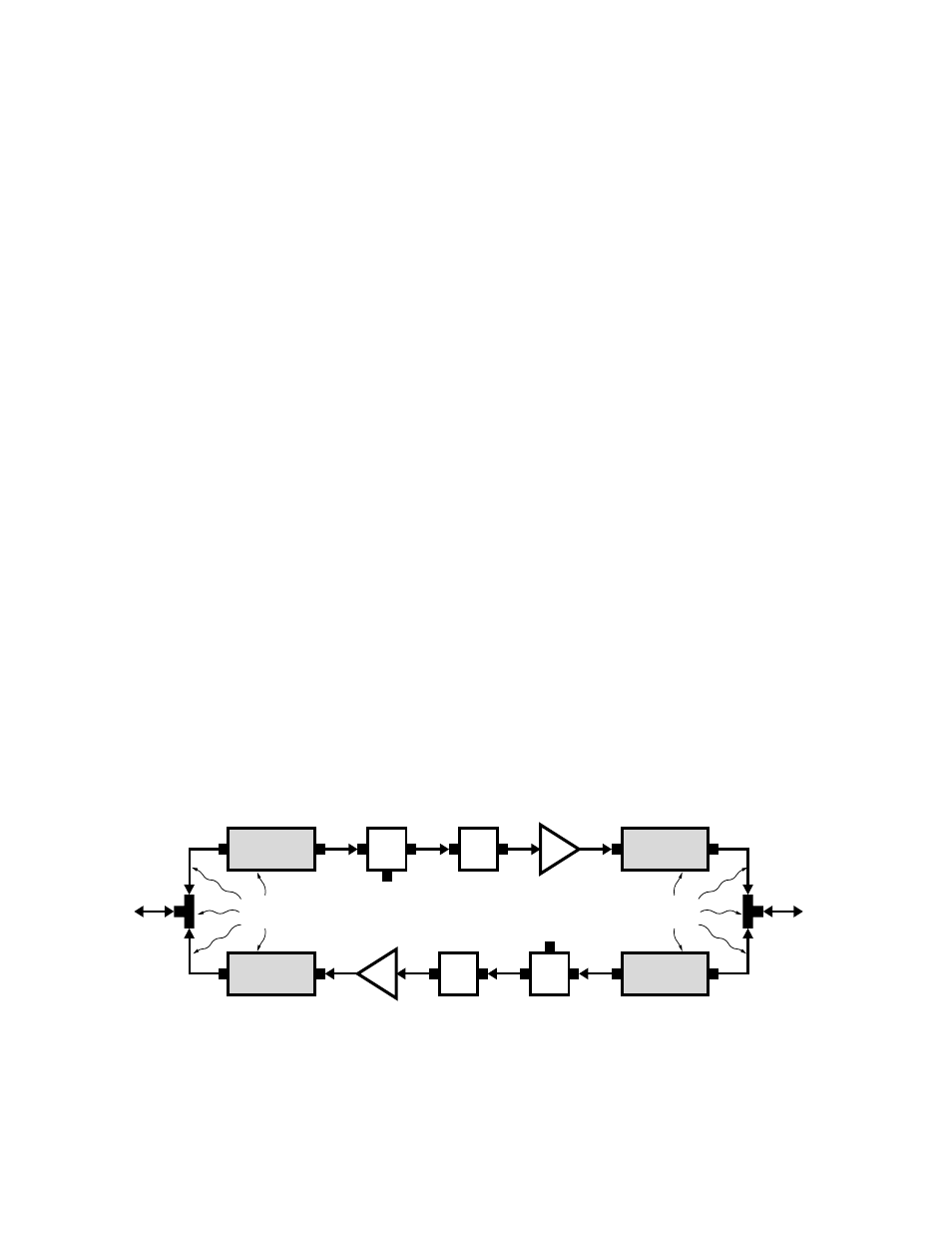
cables with the new ones. A simplified block dia-
gram for a Non-18 MHz SB II system is shown in
Figure 1. The parts to be swapped out are indi-
cated.
All work should be performed by a qualified elec-
tronics technician familiar with the communications
system. Refer to the system drawings at the back
of this manual as a guide to the correct placement
of assemblies and cables. Follow the instructions
listed below in a step-by-step fashion.
1) Open the signal booster enclosure and turn
OFF the AC power. Disconnect or turn OFF any
battery back-up DC input.
2) Disconnect three cables from the two filters on
the right side of the cabinet. Disconnect the
cables at the filter. Two of cables run to a tee-
connector and one of the cables runs to the
card cage.
3) Disconnect the signal sampler from the filter.
The right side filters should be ready for
removal at this point.
4) Disconnect three cables from the two filters on
the left side of the cabinet. Disconnect the
Signal
Sampler
Signal
Sampler
Filter
Filter
Filter
Filter
Circulator
Circulator
Test
Port
Test
Port
Amp
Amp
Replace Filters,
Cables and Tees
To
Cabinet
Connector
To
Cabinet
Connector
Replace Filters,
Cables and Tees
Figure 1: Simplified block diagram of the Non-18 MHz SB II system.