Operational check/troubleshooting, Operational check, Troubleshooting – Bendix Commercial Vehicle Systems AUTO SLACK ADJUSTER SERVICE MANUAL User Manual
Page 14: Tight or dragging brakes, Excessive chamber pushrod travel
13
Operational Check
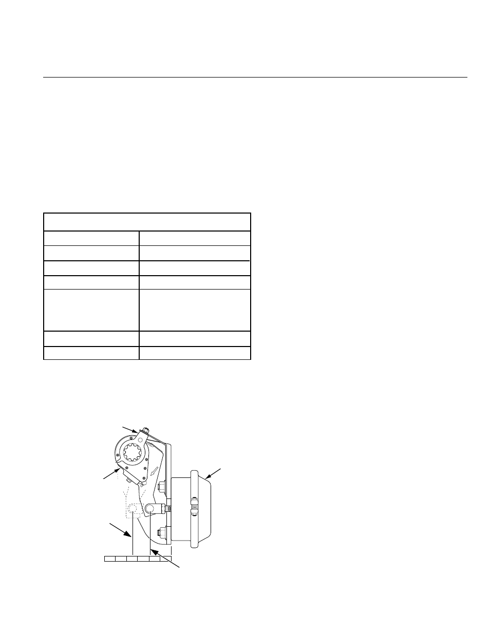
1. Measure the pushrod length (distance from the face of air chamber
to the centerline of the pushrod clevis pin) when
fully retracted, step 1. (See Figure 20.)
2. Have an assistant make an 80 to 90 psi brake application.
Measure pushrod length again, step 2.
3. Subtract the step 1 dimension from step 2. The difference
is the “applied stroke.”
4. Verify that the applied stroke is less than the maximum
specified below.
Troubleshooting
Tight or Dragging Brakes
Check foundation brake components for:
• Control arm anchor bracket not positioned properly (See brake
adjuster installation procedures.)
• Brake chamber not fully releasing
– Spring brake not fully releasing
– Pushrod binding on chamber housing
– Air supply not exhausting completely
• Out-of-round brake drums
• Extreme differences in lining-to-drum clearances
between shoes on same wheel
• Improper wheel bearing adjustment
• Broken shoe return spring
• Loose brake linings
Excessive Chamber Pushrod Travel
Check foundation brake components for:
• Loose, broken or bent control arm anchor bracket
• Worn camshaft bushings
• Loose air chamber mounting
• Binding camshaft
• Worn clutch assembly (See Checking Release Torque.)
Operational Check/Troubleshooting
Verify the correct installation of the control arm. If the self adjusting
brake adjuster does not maintain proper applied stroke, it must be
replaced.
Figure 20 Measuring Pushrod Length
5
4
3
2
1
STEP 1
RETRACTED
STEP 2
APPLIED
CONTROL
ARM
AUTOMATIC
SLACK ADJUSTER
AIR
CHAMBER
0
80-90 PSI Brake Application
Air Chamber Type
Maximum Applied Stroke
Type 36"
2-1/4"
Type 30"
2"
Type 24"
1-3/4"
Type 24"
2"
(with 2-1/2" extended
stroke)
Type 20" and 16"
1-3/4"
Type 12"
1-3/8"
SELF ADJUSTING
BRAKE ADJUSTER