Bendix Commercial Vehicle Systems AD-IS AIR DRYER AND RESERVOIR SYSTM User Manual
Page 7
7
(Recommended intervals for trucks equipped with non-
Bendix compressors are 6 months (50,000 miles), one
year (100,000 miles) and two years (200,000 miles),
respectively.)
2. Visually check for physical damage, such as chafed or
broken air and electrical lines, and broken or missing
parts.
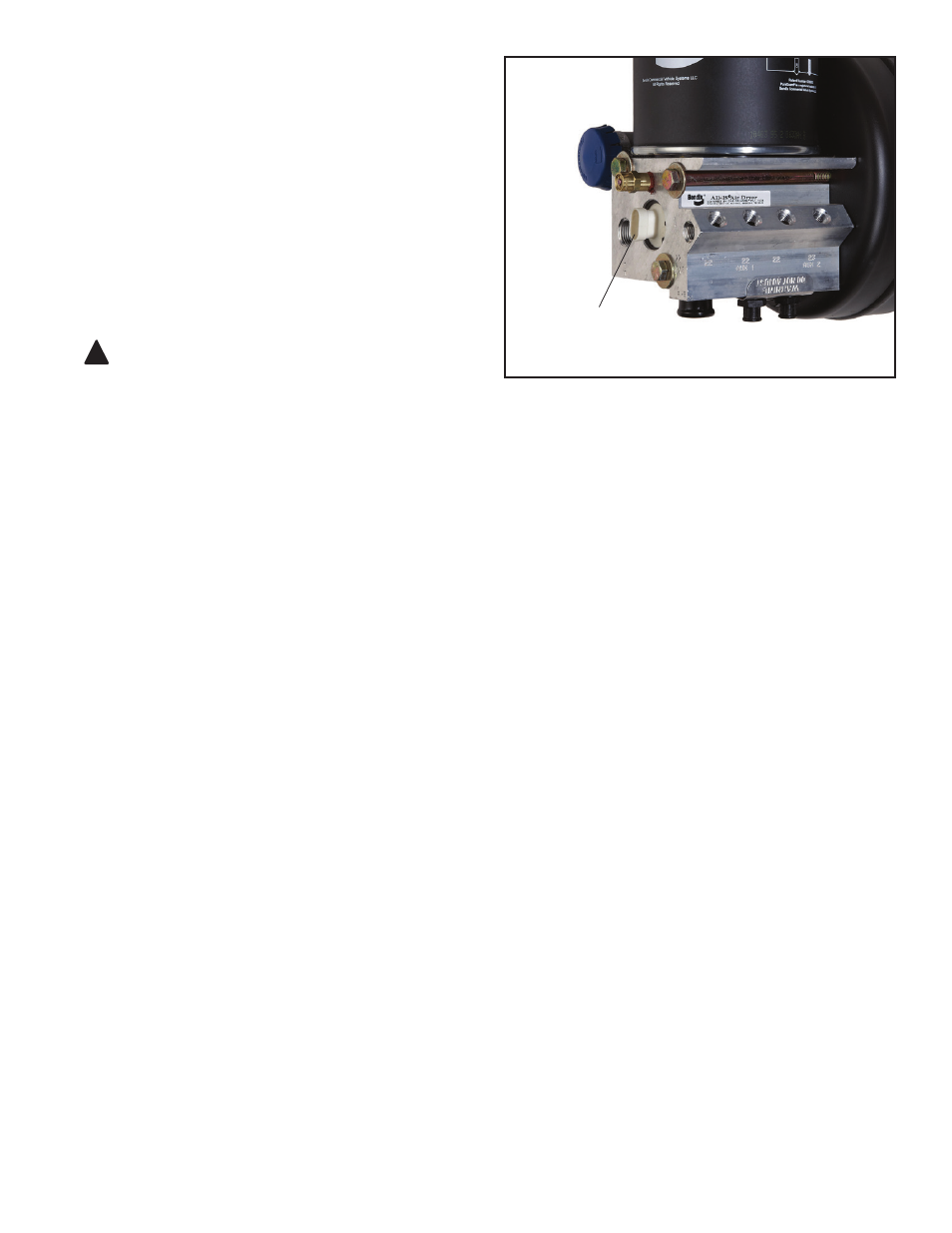
3. Check the AD-IS
®
air dryer and purge reservoir bolts for
tightness. See Figure 1. Re-torque the three air dryer
bolts to 360–420 in-lbs and the four purge reservoir
bolts to 300–360 in-lbs.
4. Perform the Operation & Leakage Tests listed in this
publication.
!
WARNING
This air dryer is intended to remove moisture and other
contaminants normally found in the air brake system.
Do not inject alcohol, anti-freeze, or other de-icing
substances into—or upstream of—the air dryer and
reservoir system. Alcohol is removed by the dryer,
but reduces the effectiveness of the device to dry air.
Use of these or other substances can damage the air
dryer and may void the warranty.
OPERATION & LEAKAGE TESTS (REFER TO THE
TROUBLESHOOTING CHART IN THIS MANUAL)
For additional information see video BW2237 — available
through the Bendix Marketing Center on www.bendix.com.
1. Check all lines and fittings leading to and from the air
dryer and reservoir system for leakage and integrity.
Repair any leaks found.
2. Build up system pressure to governor cut-out and note
that the Bendix
®
AD-IS
®
air dryer purges with an audible
escape of air. Watch the system pressure and note the
pressure fall-off for a ten minute period. If pressure
drop exceeds—a) for a single vehicle: 1 psi/minute
from either service reservoir; or b) for tractor trailer: 3
psi/minute from either service reservoir—inspect the
vehicle air systems for leak sources and repair them.
Refer to the Symptoms 1 and 4 in the Troubleshooting
Chart.
3.
CAUTION: Be sure to wear safety glasses in case
of a purge blast. Check for excessive leakage around
the purge valve with the compressor in the charge mode
(compressing air). Apply a soap solution to the purge
valve exhaust port and observe that leakage does not
exceed a 1" bubble in one second. If any leakage
exceeds the maximum specified, refer to Symptom 4
in the Troubleshooting Chart.
4. Build up system pressure to governor cut-out and note
that the AD-IS air dryer purges with an audible burst of
air, followed immediately by approximately 30 seconds
of air flowing out of the purge valve. "Fan" the service
brakes to reduce system air pressure to governor
cut-in. Note that the system once again builds to full
pressure and is followed by a purge. If the system does
not follow this pattern, refer to Symptoms 5 and 6 in
the Troubleshooting Chart .
5. Check the operation of the end cover heater and
thermostat assembly during cold weather operation as
follows:
A. Electric Power to the Dryer (Refer to Figure 4.)
With the ignition or engine kill switch in the RUN
position, check for voltage to the heater and
thermostat assembly using a voltmeter or test light.
Unplug the electrical connector at the air dryer and
reservoir system and place the test leads on each
of the connections of the female connector on the
vehicle power lead. If there is no voltage, look for a
blown fuse, broken wires, or corrosion in the vehicle
wiring harness. Check to see if a good ground path
exists.
B. Thermostat and Heater Operation
Note: These tests are not possible except in cold
weather operation.
Turn off the ignition switch and cool the thermostat
and heater assembly to below 40° F. Using an
ohmmeter, check the resistance between the
electrical pins in the air dryer and reservoir system
connector half. The resistance should be 1.5 to 3.0
ohms for the 12 volt heater assembly, and 6.0 to 9.0
ohms for the 24 volt heater assembly.
FIGURE 4 -
HEATER AND THERMOSTAT CONNECTOR
HEATER & THERMOSTAT
CONNECTOR