Warning – Bendix Commercial Vehicle Systems AD-IS AIR DRYER AND RESERVOIR SYSTM User Manual
Page 6
6
OPERATION & LEAKAGE TESTS (REFER TO THE
TROUBLESHOOTING CHART IN THIS MANUAL)
For additional information see video BW2237.
1. Check all lines and fi ttings leading to and from the air
dryer and reservoir system for leakage and integrity.
Repair any leaks found.
2. Build up system pressure to governor cut-out and note
that the Bendix
®
AD-IS
®
air dryer purges with an audible
escape of air. Watch the system pressure and note the
pressure fall-off for a ten minute period. If pressure
drop exceeds—a) for a single vehicle: 1 psi/minute
from either service reservoir; or b) for tractor trailer: 3
psi/minute from either service reservoir—inspect the
vehicle air systems for leak sources and repair them.
Refer to the Symptoms 1 and 4 in the Troubleshooting
Chart.
3. Caution: Be sure to wear safety glasses in case
of a purge blast. Check for excessive leakage around
the purge valve with the compressor in the charge mode
(compressing air). Apply a soap solution to the purge
valve exhaust port and observe that leakage does not
exceed a 1" bubble in one second. If any leakage
exceeds the maximum specifi ed, refer to Symptom 4
in the Troubleshooting Chart.
4. Build up system pressure to governor cut-out and note
that the AD-IS air dryer purges with an audible burst of
air, followed immediately by approximately 30 seconds
of air fl owing out of the purge valve. "Fan" the service
brakes to reduce system air pressure to governor
cut-in. Note that the system once again builds to full
pressure and is followed by a purge. If the system does
not follow this pattern, refer to Symptoms 5 and 6 in
the Troubleshooting Chart .
5. Check the operation of the end cover heater and
thermostat assembly during cold weather operation as
follows:
A. Electric Power to the Dryer (Refer to Figure 4.)
With the ignition or engine kill switch in the RUN
position, check for voltage to the heater and
thermostat assembly using a voltmeter or test light.
Unplug the electrical connector at the air dryer and
reservoir system and place the test leads on each
of the connections of the female connector on the
vehicle power lead. If there is no voltage, look for a
blown fuse, broken wires, or corrosion in the vehicle
wiring harness. Check to see if a good ground path
exists.
B. Thermostat and Heater Operation
Note: These tests are not possible except in cold
weather operation.
Turn off the ignition switch and cool the thermostat
and heater assembly to below 40° Fahrenheit. Using
an ohmmeter, check the resistance between the
electrical pins in the air dryer and reservoir system
connector half. The resistance should be 1.5 to 3.0
ohms for the 12 volt heater assembly, and 6.0 to 9.0
ohms for the 24 volt heater assembly.
Warm the thermostat and heater assembly to
approximately 90° Fahrenheit and again check the
resistance. The resistance should exceed 1000
ohms. If the resistance values obtained are within
the stated limits, the thermostat and heater assembly
is operating properly. If the resistance values
obtained are outside the stated limits, replace the
heater and thermostat assembly.
6. Pressure Protection Valves. Observe the pressure
gauges of the vehicle as system pressure builds from
zero. The primary or secondary gauge should rise until
it reaches approximately 106 psi (±6 psi), then level
off (or a momentary slight fall) as the next pressure
protection valve opens—supplying its reservoir. When
that pressure gauge passes through approximately 106
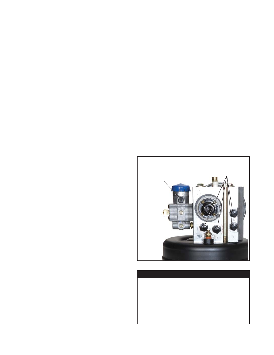
FIGURE 5 - PRESSURE PROTECTION VALVE LOCATIONS
PRESSURE
PROTECTION
VALVE
LOCATIONS
THE BENDIX
®
AD-IS
®
AIR DRYER GOVERNORS ARE
NON-ADJUSTABLE
AND FEATURES A BREATHER
VALVE IN THIS PORT
WARNING:
DO NOT ATTEMPT TO ADJUST OR
SERVICE THE PRESSURE PROTECTION
VALVES. INCORRECT PRESSURE
PROTECTION VALVE SETTINGS CAN
RESULT IN AUTOMATIC APPLICATION
OF VEHICLE SPRING BRAKES WITHOUT
PRIOR WARNING.