Port designation, Electrical control – Bendix Commercial Vehicle Systems M-30 ANTILOCK MODULATOR ASSY 9/04 User Manual
Page 8
8
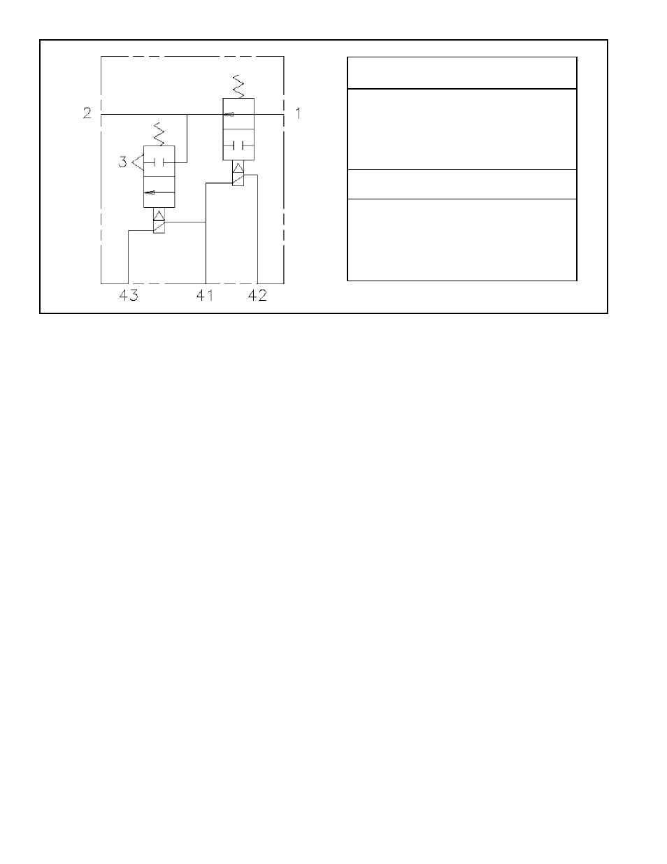
FIGURE 12: M-30
™
MODULATOR DIN SYMBOL
BW2085 © 2004 Bendix Commercial Vehicle Systems LLC All rights reserved. 9/2004 Printed in U.S.A.
2. Proceed to the modulator in question and inspect its
wiring connector. Disconnect the connector and test
the resistance between the pins ON THE MODULATOR.
Refer to figures 11 and 12.
A. HOLD TO SOURCE (41-42): Read 3.5 to 5 OHMS
B. EXHAUST TO SOURCE (43-41): Read 3.5 to 5 OHMS
C. EXHAUST TO HOLD (43-42): Read 7 to 10 OHMS
D. Individually test the resistance of each pin to vehicle
ground and note there is NO CONTINUITY.
If the resistance readings are as shown, the wire harness
leading to the modulator may require repair or
replacement. Before attempting repair or replacement
of the wire harness, refer to the test procedures specified
for the antilock controller in use for possible further testing
that may be required to substantiate the wire harness
problem. If the resistance values are NOT AS STATED,
replace the modulator.
MODULATOR REMOVAL
1.
Locate the modulator that will be replaced and clean
the exterior.
2.
Identify and mark or label all air lines and their respec-
tive connections on the valve to facilitate ease of
installation.
3.
Disconnect both air lines and the electrical connector.
4.
Remove the modulator from the vehicle.
5.
Remove all air line fittings and plugs. These fittings
will be re-used in the replacement modulator.
PORT DESIGNATION
SUPPLY
1
DELIVERY
2
EXHAUST
3
ELECTRICAL CONTROL
SOURCE 41
HOLD 42
EXHAUST 43
MODULATOR INSTALLATION
1.
Install all air line fittings and plugs, making certain thread
sealing material does not enter the valve.
2.
Install the assembled valve on the vehicle.
3.
Reconnect both air lines to the valve using the identifi-
cation made during VALVE REMOVAL step 5.
4.
Reconnect the electrical connector to the modulator.
5.
After installing the valve, test all air fittings for excessive
leakage and tighten as needed.
TECHNICAL INFORMATION
Porting
1 Supply Port (from brake, relay
or quick release valve) - 1/2" NPT
1 Delivery Port (brake actuator) - 1/2" NPT
Optional:
Push-to-connect for 1/2" tubing
Solenoid Voltage : 12 Volts DC Nominal
Weight: 1.7 pounds
Maximum Operating Pressure: 150 psi Gauge
Operating Temperature Range: -40 to 185 degrees
Fahrenheit
Pressure Differential: 1 psi maximum (supply to delivery)
Mounting Hole Sizes
0.33" diameter thru body