Rear axle system, Functional check, Operation – Bendix Commercial Vehicle Systems M-30 ANTILOCK MODULATOR ASSY 9/04 User Manual
Page 2: Front axle systems, Non antilock hold, Non antilock exhaust, Non antilock application
2
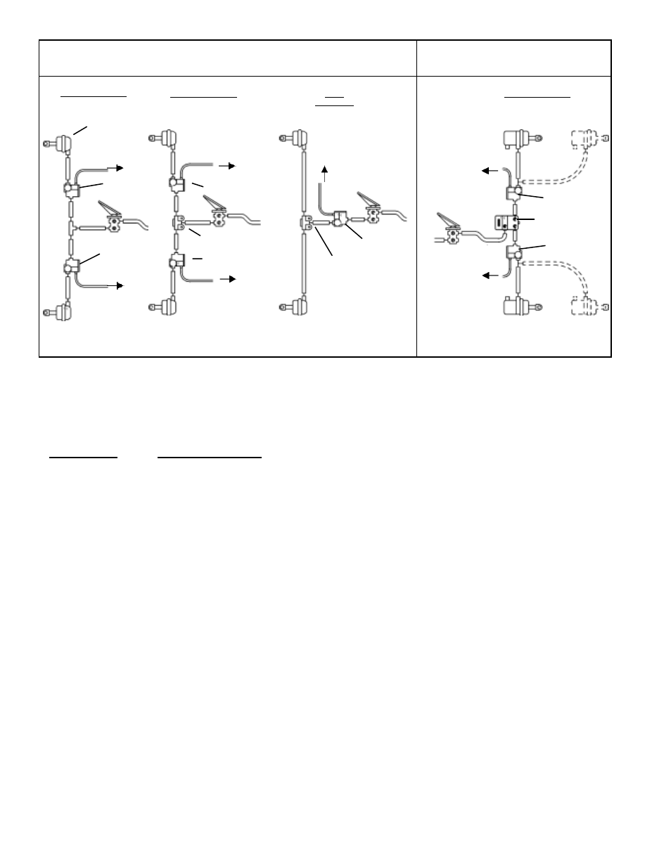
FIGURE 4: TYPICAL WHEEL AND AXLE CONTROL SYSTEMS
NOTE: USE OF A QUICK RELEASE VALVE IS NOT TYPICALLY REQUIRED WITH THE M-30
™
MODULATOR. REFER TO VEHICLE SPECIFICATIONS FOR
RECOMMENDED CONFIGURATION.
exhaust diaphragm. Air pressure, along with spring force,
seats the exhaust diaphragm on the exhaust passage, thus
preventing the escape of service air. Simultaneously,
application air flows to the supply diaphragm and forces it
away from its seat. Air flows past the open supply port and
out the modulator delivery port to the service brake chambers.
NON ANTILOCK HOLD
(FIGURE 6)
When the desired air pressure is attained in the service
brake chambers, the brake system is in the Holding position.
In the Holding position, both solenoids in the modulator
remain de-energized and the balance of the internal
components remain in the same position as they assumed
during application.
NON ANTILOCK EXHAUST
The manner in which air exhausts through the modulator
differs, depending upon how rapidly the brake application is
released by the driver.
Normal Exhaust (Figure 7) - During a normal, relatively
"slow" brake release, air moves back through the modulator
in the reverse direction as it flowed during application. The
internal components of the modulator will remain in the same
position as they assumed during application until air pressure
decreases to approximately one half psi, at which time the
supply diaphragm will seat on the supply passage. A
relatively small amount of air will generally be expelled from
the modulator exhaust port during "slow" brake release.
REAR AXLE SYSTEM
The Supply, Delivery and Exhaust ports on the M-30
™
modulator are identified with a cast, embossed numeral for
positive identification.
Identification
Air Line Connection
1, SUP
Supply
(incoming air from foot, relay or quick release valve)
2, DEL
Delivery
(air delivery to service actuators)
3, EXH
Exhaust
FUNCTIONAL CHECK
A wiring harness connects the vehicle modulators to the
controller. The ABS controller is able to simultaneously and
independently control the individual modulators. When
vehicle power is supplied to the ABS ECU, a modulator "chuff"
test is performed. When the brake pedal is depressed and
the ignition turned on, the modulator "chuff" test can be
heard. This test will verify if the modulator is functioning
pneumatically correct. The modulators will exhaust air in
the sequence of right front, left front, right rear, left rear. If
they do not follow this sequence, proceed with modulator
troubleshooting.
OPERATION
NON ANTILOCK APPLICATION
(FIGURE 5)
During normal, non antilock braking, both solenoids are
de-energized (no electrical power). Brake application air
enters the Supply port of the modulator and flows to the
FRONT AXLE SYSTEMS
AXLE
CONTROL
WHEEL CONTROL
WHEEL CONTROL
SERVICE
BRAKE
CHAMBER
M-30
™
MODULATOR
M-30
™
MODULATOR
QUICK RELEASE VALVE
M-30
™
MODULATOR
SERVICE
BRAKE
CHAMBER
SERVICE &
SPRING
BRAKE
CHAMBER
QUICK RELEASE VALVE
TO
ANTILOCK
CONTROLLER
CONTROLLER/
RELAY
ASSEMBLY
M-30
™
MODULATOR
M-30
™
MODULATOR
TO
ANTILOCK
CONTROLLER
TO
ANTILOCK
CONTROLLER
TO ANTILOCK
CONTROLLER
TO ANTILOCK
CONTROLLER
OR
SERVICE
BRAKE
CHAMBER
M-30
™
MODULATOR
TO
ANTILOCK
CONTROLLER
M-30
™
MODULATOR
SERVICE
BRAKE
CHAMBER
WHEEL CONTROL
OR
TO ANTILOCK
CONTROLLER