Operation – Bendix Commercial Vehicle Systems ATR-1 ANTILOCK TRACTION RELAY 02/11 User Manual
Page 2
2
ATR-1
™
ANTILOCK
TRACTION RELAY
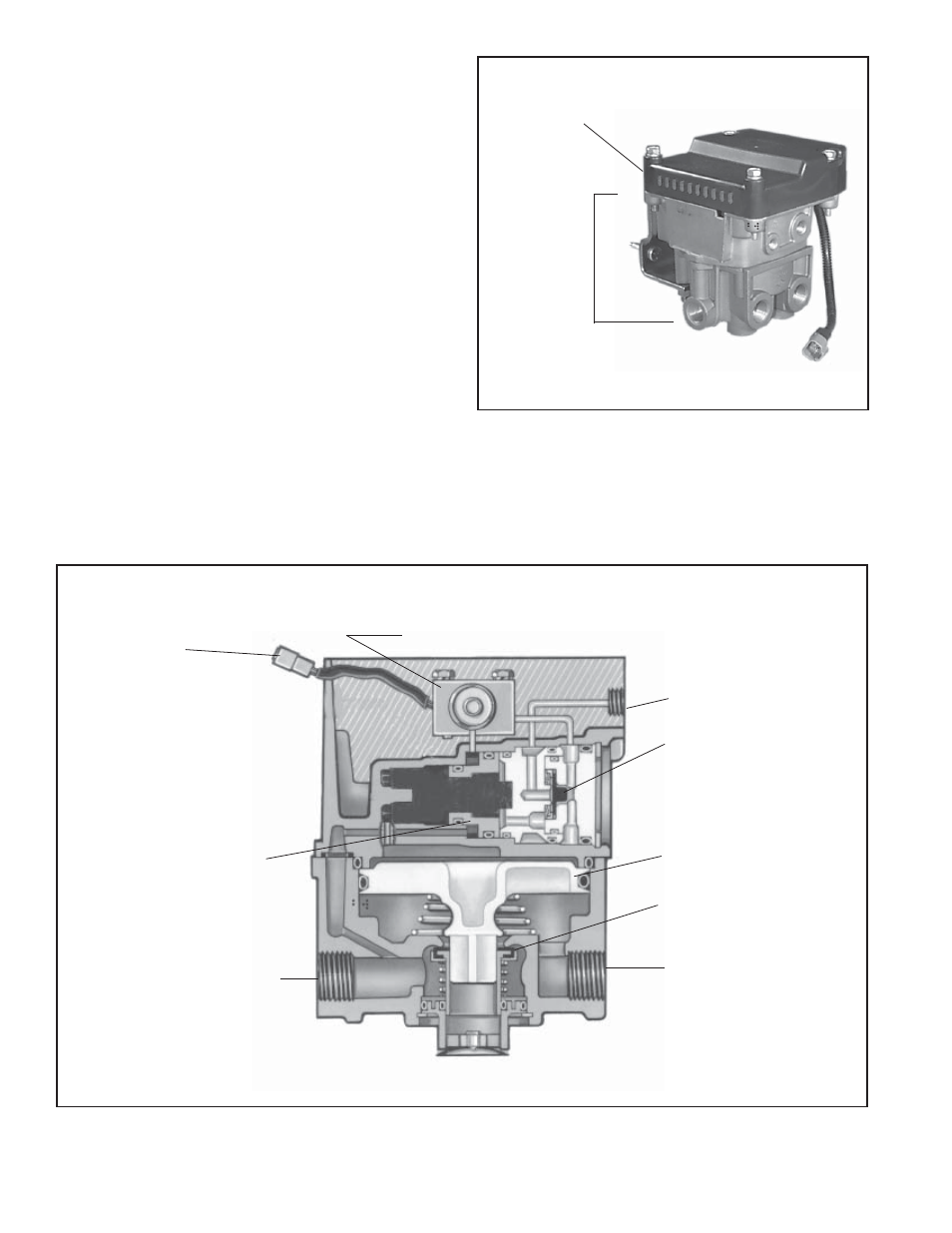
VALVE
CONTROLLER
FIGURE 2 - ANTILOCK TRACTION ASSEMBLY
TRACTION CONTROL
SOLENOID
SUPPLY
SERVICE
DOUBLE
CHECK VALVE
DELIVERY
EXHAUST
RELAY PISTON
INLET-EXHAUST
VALVE
BLEND BACK
PISTON
SOLENOID
CONNECTOR
FIGURE 3 - ATR-1
™
ANTILOCK TRACTION ASSEMBLY
OPERATION
GENERAL
Because the ATR-1
™
is essentially a relay valve, the following
description of operation refers to its function in the vehicles
air brake system and does not address all of the separate
antilock components and their operation. For a description
of antilock operation, refer to the appropriate Service Data
Sheet covering the electronic controller used with the
ATR-1
™
valve.
SERVICE BRAKES APPLYING (FIGURE 4)
Reservoir air pressure is present at the supply port and
fl ows through internal body and cover passages to the
supply of the normally closed (NC) traction control solenoid.
Brake application air enters the ATR-1
™
valve’s service
port and is conducted to the single check valve. The check
valve diaphragm fl exes in response to application pressure
and seals the passage to the open exhaust of the traction
solenoid. Air fl ows through the service piston then through
the center of the blend back and through a passage in the
cover to the top of the service relay piston. In response
to air pressure, the relay piston moves into contact with
the exhaust portion of its inlet and exhaust valve. With
the exhaust passage sealed, continued movement of the
piston unseats the inlet portion of the inlet and exhaust
valve, allowing supply air from the reservoir to fl ow out
the ATR-1
™
valve’s delivery ports to the brake chambers.