Bendix Commercial Vehicle Systems MV-3 DASH CONTROL MODULE 3/04 User Manual
Page 6
6
ASSEMBly
DuAl CIRCuIT SuPPly VAlVE
1. lubricate all o-rings and bores with silicone lubricant.
(Bendix piece number 291126 or Dow Corning 55-M.)
2. Place the check valve (17) into its seat in the body with
its flat surface facing upward. If necessary, reach into
the body to make sure the valve is seated evenly in the
bore.
3. Install o-rings (24 & 13) onto the check valve (23). Then
install the assembly into its cavity in the Bendix
®
MV-3
®
valve body.
4. Install the snap ring (22) making sure it is fully seated
in its groove.
SPOOlS
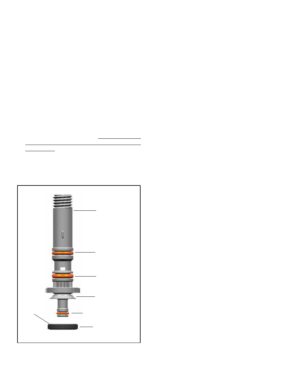
1. Install o-rings (18,19 & 20) and the exhaust seal (21)
onto the stem of the plungers (15).
CAuTION: The exhaust seal (21) must be installed so
that its beveled surface mates with the beveled surface
of the plunger (Figure 7).
2. Install the o-ring (16) onto the guide spool (14). Install
the guide spool assembly over the threaded end of the
plunger (15) and press down firmly until it contacts the
plunger flange.
FIGURE 7 -
PlunGer and exhaust seal
i.D.
BeVel
21
eXhauSt Seal
20
o-rinG
MatinG
eXhauSt
Seal
BeVel
19
o-rinG
18
o-rinG
15
PlunGer
3. Install the spring (12) over the boss in the bottom of
the spool cavity in the body of the MV-3 valve. Place
the spool assembly into the body, keeping the spool
square to the body press and turn the stem until the
spool is fully seated in its cavity. Note the assembly is
keyed and may only be installed one way.
4. Repeat Steps 1, 2, and 3 with the remaining components
for the opposite spool.
ShuTTlE AND ChECk VAlVE
1. Install the o-ring (11) into its groove on the piston (7) and
o-ring (6) onto the cap (5).
2. Install the spring (8) on the piston (7) and spring (9) on
the boss of the check valve (10).
3. Install the spring and check valve into its cavity in the
body of the MV-3 valve (tapered end of check valve to
enter cavity first). Make sure the spring (9) is centered
in the bore.
4. Install the piston assembly into the cavity making sure
the spring (9) mates with the bore of the piston.
5. Install the cap (5) with o-ring (6).
FINAl ASSEMBly
1. Install the cover plate (3) onto the valve body and retain
with the six Phillips head screws. Torque to 30 in. Ibs.
2. Attach the red (1) and yellow (2) buttons onto the
threaded stems of the spools, making sure that they are
oriented correctly as noted in Step 1 of Disassembly
procedure.
3. Reattach the MV-3 valve to the dash using the hardware
removed in Step 2 of Disassembly. If air lines were
removed during disassembly, reconnect to ports marked
during disassembly. When reconnecting threaded ports
use a liquid thread sealing compound, attach the air
line until it is hand tight and then turn approximately
one and a half turns further (or using a maximum of 10
ft.-lbs. torque - Note: overtorquing will crack the port).
SERVICE TEST
Repeat the Operational Test procedures. Test drive vehicle
at slow speed in a safe area prior to placing it back into
service.
For additional information refer to Technical Bulletin -
Bendix Dash Valve Trip Pressure TCH-003-051.