Baumfolder BAUM20: Ifold Service Manual User Manual
Page 8
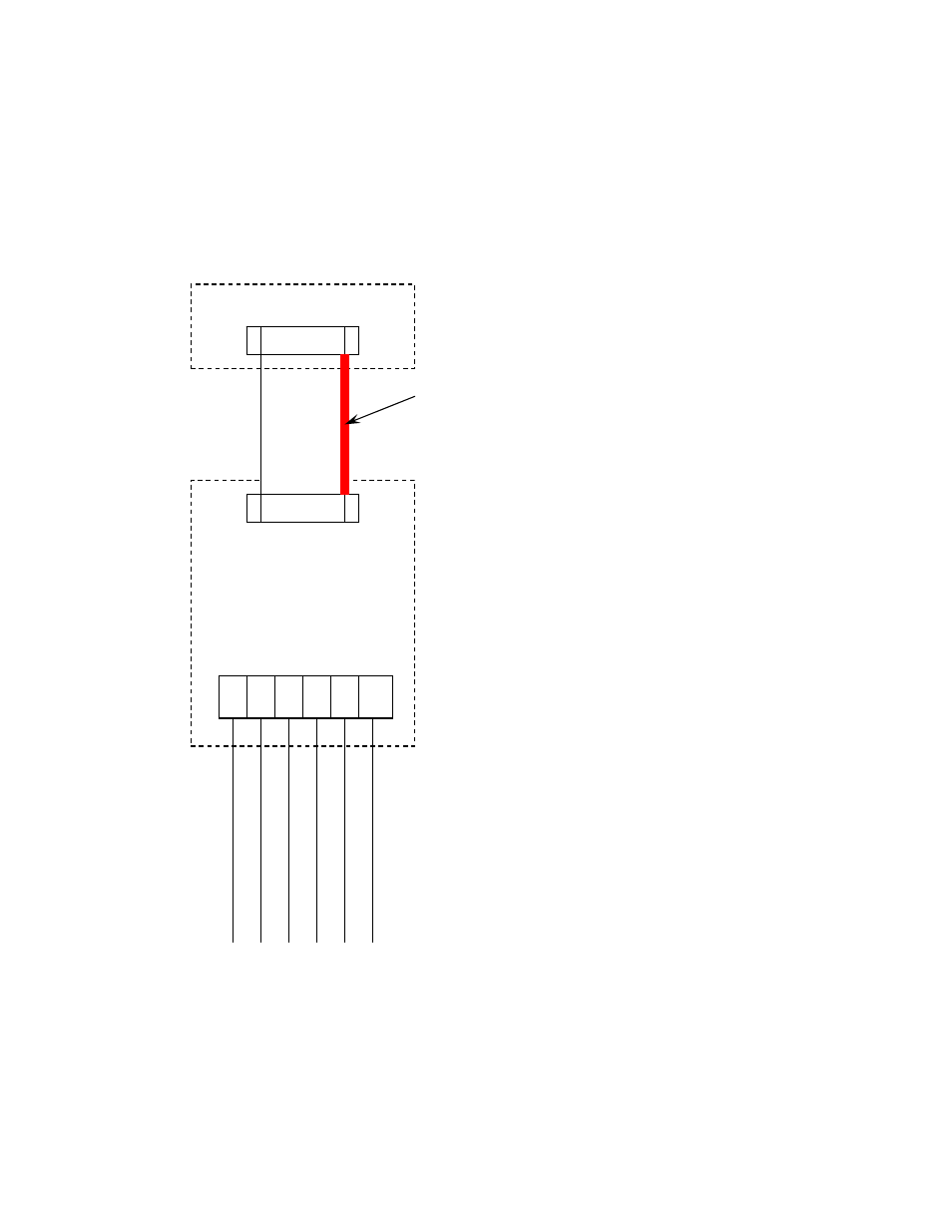
Figure 6
1
2
3
4
9
10
Ribbon
Cable
Communication
Board
Communication
Cable
Term
inal Block
DCT500
Pink
Gray
Brown
W
h
ite
Yellow
Green
X27
O
ri
en
ta
ti
on
S
tr
ip
e
12.
Add ribbon cable. Connect one end to the communication board as shown in Figure 5.
Note
orientation stripe on
the ribbon cable, thi
s must be
on the lef
t side of c
onnector as shown.
The connector can be inst
alled backwards
.
Run cable and connect to the X27 connector on the DTC500 board, see Figure 9.
Note
orientation stripe on the
ribbon cable, this must be on the left side of the X27 connector as shown.
The connector can be installed
backwards.
Secure the ribbon cable with wire ties, NOTE: do not over tighten or crush the ribbon cable with the
wire ties.
13.
Add new fuse blocks to the din rail to the right of the existing fuse blocks as shown in Figure 7, The fuse blocks must be tied together with a tie pin, this will insure that both fuse holders will open at the same time. Label fuse
blocks as A-F1 and A-F2.
NOTE: DO NOT INSTALL FUSES AT THIS TIME.
Run I-fold power cable between
transformer and the terminal blocks and into the wire channel. Run cable to the bottom side of fuses. Add an
extra 2” to 3” of cable, and then cut cable to that length. Strip back approximately 8” of cable jacket. Strip approximately 5/16” of wire insulation from each conductor. Add ring terminal to the green \ yellow conductor
and mount to ground lug shown in Figure 7. Wire conductor 1 to bottom of fuse block A-F1 and wire conductor 2
to bottom of fuse block A-F2.
6
Page 6 of 45
TP10497