Baumfolder BAUM20: Pile Folder 1st Station (from 2002 thru 2004) User Manual
Page 8
TP10243-2
PAGE 8
ELECTRICAL CONNECTIONS
1.0 Wiring the Pump (2020 / 3 phase)
Connect the pressure/vacuum pump at the pump
junction box (Figure 5) using the attached cable. Follow the
instructions below for the proper connections.
There are six wires from the control box to the pump.
Wire #1 connects to the pump motor wires #1 & #7. Wire #2
connects to the pump motor wires #2 & #8. Wires #3
connects to the pump motor wires #3 & #9. Wires #4 & #5
connect seperately to the two pump motor wires marked
"THERMAL". Wire #6 is not used and should be taped off.
The remaining pump motor wires #4, #5, & #6 should be
connected together with a wire nut. The green wire is the
ground that is attached to the motor frame.
Turn the main power switch to the "ON" position.
Switch the pump on momentarily and check for proper
pump rotation as indicated by the rotation arrow on the
pump. Immediately turn off the pump if the rotation is
wrong.
If the rotation is incorrect interchange any two of the
three wires #1, #2, or #3 in the pump motor terminal box.
1.1 Wiring the Pump (2020 / 1 phase)
Connect the pressure/vacuum pump at the pump
junction box (Figure 5) using the attached cable. Follow the
instructions below for the proper connections.
There are six wires from the control box to the pump.
Wire #1 connects to the terminal marked 1 in the pump
motor. Wire #2 connects to the terminal marked 4 in the
pump motor. Wires #3 ,#4 ,#5 & #6 are not used and should
be taped off separately. The green wire is the ground that is
attached to the motor frame.
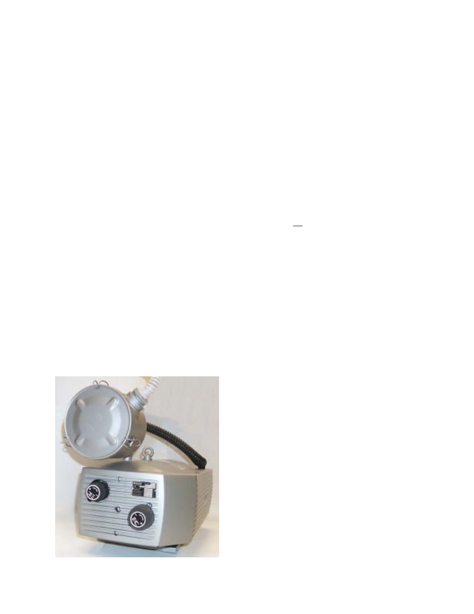
Figure 5
1.2 Other Connections
Refer to the serial number plate for electrical
requirements. The serial number plate notes the voltage,
phase and hertz, minimum time delay fuse, total machine
amperage, and minimum wire conductor size for the main
power connection.
The main power is connected directly to the line side of
the main power switch. In a 2020 single phase use L1 and
L2 only.
All electrical connections are to be made by a certified
electrician. Refer to local building electrical codes for proper
and safe connections.
For the following items, refer to Figure 6. Run a power
cable from your distribution box to the main control box on
the pile feeder. Turn the main power switch to zero. Using
the appropriate tool, open the latches on the control box
door and open the door.
NOTE: The door is connected to the main box by a ground
wire that should not be removed.