Installation – AJA R10CE User Manual
Page 6
6
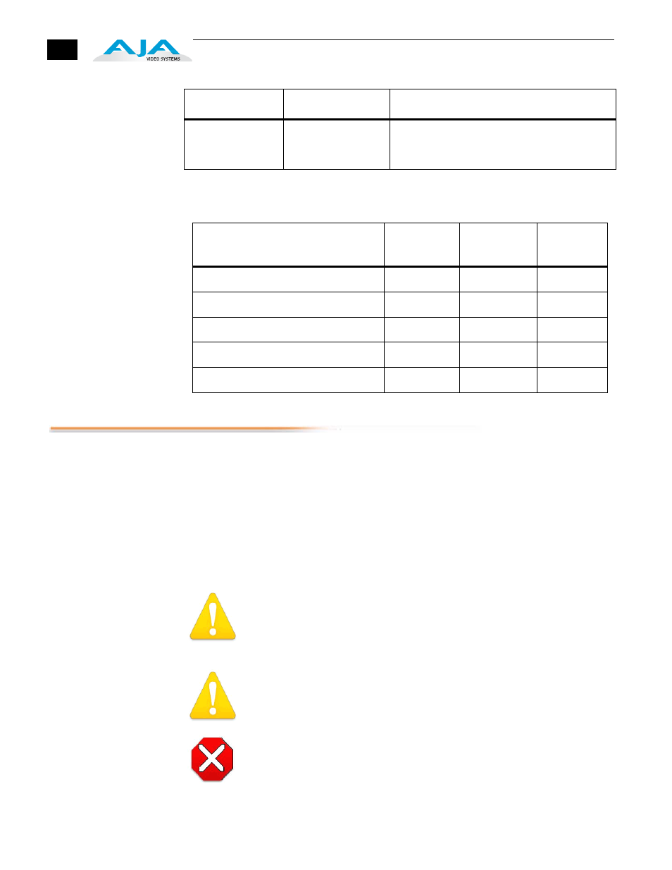
Output Selection
Matrix For Output
3 BNCs
The following table shows the combinations of DIP switch settings required to
choose output formats for the three configurable output BNCs.
Installation
Typically, R10CE installation consists of the following:
1.
disconnect power from the frame (remove line cord)
2.
remove the FR1/FR2 front panel
3.
install R10CE card module
4.
apply external color black reference at the frame’s External Reference BNC
5.
replace the FR1/FR2 front panel
6.
apply power to the frame by connecting a north american-style power cord
from the frame to mains power (90 to 260 VAC)
!
Warning!
Ensure Mains Power is disconnected before installing the FR1 or FR2 frame R-
series modules into the frame, or installing and removing options. If a Mains
switch is not provided, the power cord(s) of this equipment provide the means of
disconnection. The socket outlet must be installed near the equipment and must
be easily accessible.
Warning!
FR2 Dual Power Cord Notice—please read this. To reduce the risk of electrical
shock, disconnect both power cords before servicing equipment.
Caution!
The FR1/FR2 front fan door is heavy and is not hinged. Remove with Caution.
Instructions for removing the frame front door for module installation is discussed in
the
FR1/FR2 User Manual.
S6 — TEST
Enable or disable
test pattern output
OFF (UP) = Disables internal test signal
ON (DOWN) = Selects internal 75% colors bars
test signal
Switch Number
Description
Details
Output Format
DIP Switch
#1
DIP Switch
#2
DIP Switch
#3
3 Composite
CMPSTE
RGB
N/A
1 Composite and 1 Y/C
CMPSTE
YPbPr/YC
N/A
RGB
CMPNT
RGB
N/A
SMPTE component (BETA625)
CMPNT
YPbPr/YC
SMPTE
BETA 525 component
CMPNT
YPbPr/YC
BETA