User controls – AJA R10CE User Manual
Page 5
1
5
AJA Universal Monitoring D/A Converter User Manual
User Controls
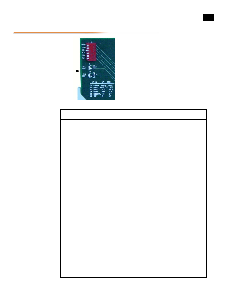
The user interface for configuring the R10CE and
selecting output formats is a 6-position DIP switch
at the front of the card. Two LEDs at the front of the
card additionally show the type of input present
(525 or 625), which happens automatically.
The four outputs labeled
Serial Out
1-4 are always
serial digital. They are cable-equalized, and
reclocked. The “Comp” outputs are format
configurable via the S1 and S2 DIP switches. All DIP
switch functions are described below under
Control
Functions
.
Control Functions
LEDs
DIP
Switch
Switch Number
Description
Details
S1 — CMPNT or
CMPST
Choose Y/C or
Composite Format
CMPNT (UP) = Select component output
CMPST (DOWN) = Select composite output
S2 — YPbPr/YC
or RGB
Configure
Component Output
YPbPr/YC (UP) = Output Y, R-Y, B-Y if SW1 is
COMPNT. If SW1 is CMPST, output 1 composite
& 1 Y/C
RGB (DOWN) = Output RGB if SW1 is
COMPNT. If SW1 is CMPSTE, output 3
composites.
S3 — BETA or
SMPTE
Configure
Component Levels
BETA (UP) = Selects BETA 525 levels (if
configured for Component output)
SMPTE (DOWN) = Selects SMPTE levels (if
configured for Component output) NOTE: No
effect with 625 input
S4 — NAR or
WIDE
Configure Blanking
NAR (Up) = Vertical (line numbers indicate where
video starts)
line 13, field 1; line 12, field 2 (525 line)
line 10, field 1; line 322, field 2 (625 line)
Horizontal (active video line durations)
ITU-R.470 (720 pixels PAL/NTSC)
WIDE (Down) = Vertical (line numbers indicate
where video starts)
line 22, field 1; line 21, field 2 (525 line)
line 23, field 1; line 335, field 2 (625 line)
Horizontal (active video line durations)
ITU-R/SMPTE (710 pixels NTSC, 702 pixels
PAL)
S5 — PEDESTAL
Set pedestal for
Composite outputs
(only). Note: there is
no effect with 625
input.
ON (UP) = 7.5 IRE pedestal for NTSC
.:
OFF (DOWN) = No pedestal for NTSC-J