User controls – AJA RH10MD User Manual
Page 5
1
5
AJA RH10MD HD Down Converter and DA User Manual
User Controls
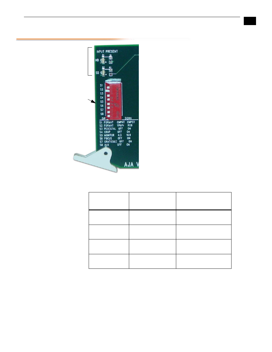
The user interface for configuring the RH10MD and
selecting output formats is a dipswitch at the front
of the card and some jumpers at the back of the
card. Two LEDs at the front card additionally show
the type of input present (HD or SD).
The four outputs labeled
DA Out
1-4 are always
serial digital, either HD or SD, depending on the
input format detected. They are cable-equalized,
and reclocked. The four outputs labeled
SD Out
1-4
may be configured as either SDI or analog via 4
jumpers on the circuit board. These jumpers are
located at the end of the board next to the large
backplane connector where the card plugs into an
FR1/FR2 chassis. These jumpers are labeled as “1”,
“2”, “3”, or “4”, corresponding to the four SD output
BNCs. This arrangement supports any combination
of SDI or analog output. For example, 4 SDI, 4
composite, 2 SDI and 2 composite, etc. If a jumper
is set for analog, then the corresponding output is
defined by the dipswitch settings of S1, S2, and S8
as shown in the table below.
A jumper (J2) on the card allows you to select
further options described later.
S1 = Component
(UP)
S1 = Composite (Down)
SD Out 1
Y if S2 = YPbPr (up)
G if S2 = RGB (down)
Composite
SD Out 2
Y if S2 = YPbPr (up)
G if S2 = RGB (down)
Composite
SD Out 3
Cb if S2 = YPbPr (up)
B if S2 = RGB (down)
Composite if S8 = up
Y of YC pair if S8 = down
SD Out 4
Cr if S2 = YPbPr (up)
R if S2 = RGB (down)
Composite if S8 = up
C of YC pair if S8 = down
LEDs
DIP
Switch