AJA HD10CEA User Manual
Page 5
1
5
AJA HD10CEA SDI/HD-SDI to Analog Audio/Video Converter
Note:
The composite, S-video, component beta and pedestal switches (Switches 1
through 3) only function when the input is Standard Definition SDI. When supplied
with HD-SDI, only component SMPTE or RGB video output is possible from the
HD10CEA.
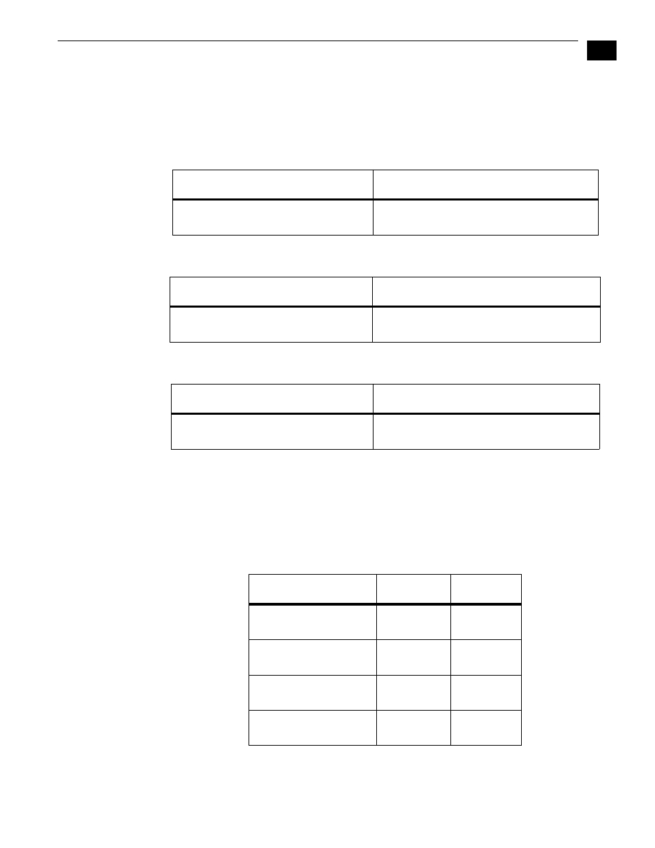
Switch 1—Selects YPbPr/YC or RGB Component Outputs
:
Switch 2—Select Component (COMPNT) or Composite (CMPSTE) Out
:
Switch 3—Configure Pedestal For Composite
:
Note:
There is no effect with 625 input.
Switches 4 and 5—Select an Audio Channel Group for Output
Together these two switches select the group of audio channels that will be routed to
the XLR connectors on the break-out cable. Each audio group has four channels,
corresponding to the four connectors. The following table shows the group and
channel assignments selected by each switch position for the two DIP switches.
:
RIGHT
LEFT (default)
RGB:
Selects RGB
YPbPr/YC:
Selects YPbPr/YC component video out
RIGHT
LEFT (default)
CMPSTE:
Selects composite video output
COMPNT:
Selects component video output
RIGHT
LEFT (default)
7.5 IRE pedestal for NTSC (also selects
BETA 525 levels for YPbPr)
No pedestal (also selects SMPTE levels for
YPbPr)
Group and Channels
S4
S5
Group 0 (default):
Channels 1 to 4
0ff (Left)
0ff (Left)
Group 1:
Channels 5 to 8
0n (Right)
0ff (Left)
Group 2:
Channels 9 to 12
0ff (Left)
0n (Right)
Group 3:
Channels 13 to 16
0n (Right)
0n (Right)